Supercharge Your Innovation With Domain-Expert AI Agents!

Steel plate cutting method and device

A cutting method and cutting device technology, applied in the direction of shearing devices, shearing machine accessories, shearing machine equipment, etc., can solve problems such as calibration errors, steel plate cutting deviations, steel plate cutting size deviations, etc., to ensure accuracy and accuracy Cutting, the effect of improving precision

Inactive Publication Date: 2016-05-18
ELECTRON CO LTD
View PDF6 Cites 5 Cited by
  • Summary
  • Abstract
  • Description
  • Claims
  • Application Information

AI Technical Summary

Problems solved by technology

[0003] The accuracy of the cutting size of the steel plate depends on the calibration of the size of the entrance measuring roller 1 and the exit measuring roller 5. However, in actual application, the entrance measuring roller 1 and the exit measuring roller 5 wear out quickly during use, and the entrance measuring roller after wear Roller 1 and outlet measuring roller 5 often cause calibration errors when used, resulting in deviations in steel plate cutting
At the same time, when the cylinder pressure of the measuring roller is unstable, it is easy to cause deviations in the cutting size of the steel plate

Method used


Image

  • Steel plate cutting method and device
  • Steel plate cutting method and device

Examples


Embodiment Construction

[0030] The steel plate cutting method and the device thereof provided by the embodiments of the present invention are used to realize accurate cutting of steel plates and improve the precision of steel plate cutting.

[0031] In order to enable those skilled in the art to better understand the technical solutions in the embodiments of the present invention, and to make the above-mentioned purposes, features and advantages of the embodiments of the present invention more obvious and understandable, the technical solutions in the embodiments of the present invention are described below in conjunction with the accompanying drawings The program is described in further detail.

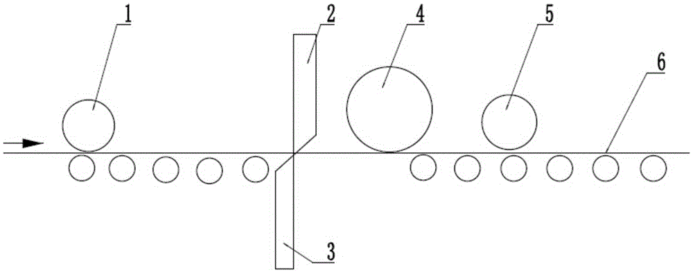
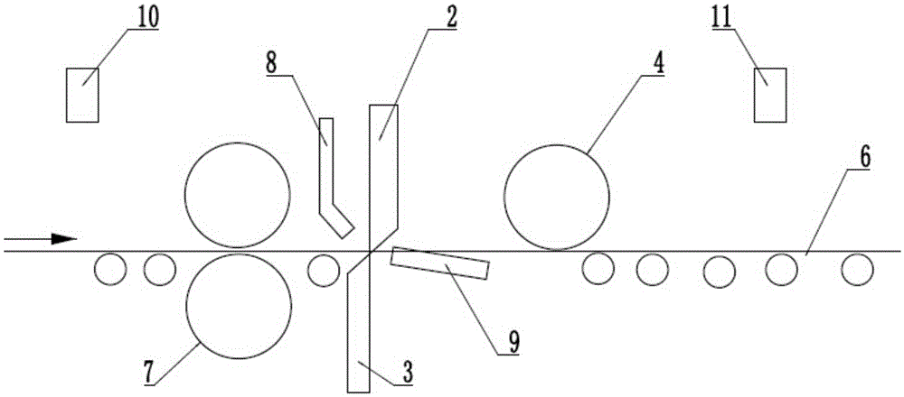
[0032] A kind of steel plate cutting method that the embodiment of the present invention provides, its method comprises:

[0033] Obtain the horizontal distance L between the entrance laser velocimeter 10 and the upper cutting edge 2 1 , to obtain the horizontal distance L between the exit laser velocimete...


PUM


Abstract

The invention discloses a steel plate cutting method which comprises the following steps: acquiring the horizontal distance L1 between an entrance laser speed meter and an upper shear blade, acquiring the horizontal distance L2 between an exit laser speed meter and the upper shear blade, acquiring the total length B of a steel plate on a roller table, and acquiring the length L of the to-be-cut part of the steel plate; acquiring a steel plate cutting command of head cutting, tail cutting or segmenting; when the steel plate cutting command of head cutting or segmenting is acquired, acquiring the running speed V1 at the front end of the steel plate by the entrance laser speed meter, calculating the running time t1 of the steel plate according to the formula t1=(L+L1) / V1, and then carrying out cutting by the upper shear blade; and when the steel plate cutting command of tail cutting is acquired, acquiring the running speed V2 at the front end of the steel plate by the exit laser speed meter, calculating the running time t2 of the steel plate according to the formula t2=(B-L-L2) / V2, and then carrying out cutting by the upper shear blade. The invention further provides a steel plate cutting device. By adoption of the steel plate cutting method and device, the steel plate can be accurately cut and the steel plate cutting precision can be improved.

Description

technical field [0001] The invention relates to the technical field of steel plate cutting, and more specifically, relates to a steel plate cutting method and a device thereof. Background technique [0002] In the production process of steel plate, it is often necessary to cut, such as head, tail, segmentation, etc., to obtain the required size. At present, the cutting of the steel plate is mainly to use the attached figure 1 In the device shown, the steel plate runs in the direction of the arrow in the figure. When the position of the steel plate moves to a suitable position, the upper cutting edge 2 and the lower cutting edge 3 are used together to cut the steel plate running on the roller table 6. During the entire cutting process Among them, the entrance measurement roller 1 and the exit measurement roller 5 are used to monitor the steel plate cutting size, control the length and cutting position of the steel plate, and the exit pressure roller 4 is set in the cutting d...

Claims


Application Information

Patent Timeline
Patent Type & Authority Applications(China)
IPC IPC(8): B23D15/08B23D33/00
CPCB23D15/08B23D33/00
Inventor 柳希泉吕霞刘疆邱芳庄宁宁翟诺闫仲科石荣鹏赵亮桑森王静
Owner ELECTRON CO LTD
Features
  • R&D
  • Intellectual Property
  • Life Sciences
  • Materials
  • Tech Scout
  • Unparalleled Data Quality
  • Higher Quality Content
  • 60% Fewer Hallucinations
Learn More