Positioning method for integrated guide vane

A technology of guide vane and positioning method, which is applied in the field of machining, can solve the problems of misalignment of positioning datum and design datum, error, and scrapping of blade size out of tolerance.

Active Publication Date: 2016-05-18
SHENYANG LIMING AERO-ENGINE GROUP CORPORATION
View PDF9 Cites 7 Cited by
  • Summary
  • Abstract
  • Description
  • Claims
  • Application Information

AI Technical Summary

Problems solved by technology

However, the disadvantage of this method is that after the blade is deformed, the positioning datum and the design datum will not coincide, resulting in positioning errors, that is, it cannot ensure that the blade is in the correct position on the measuring tool or fixture, which will cause the blade to be damaged during the finishing or processing process. Medium size out-of-tolerance scrapping

Method used


Image

  • Positioning method for integrated guide vane
  • Positioning method for integrated guide vane
  • Positioning method for integrated guide vane

Examples


Embodiment 1

[0023] Taking the triple guide vane as an example, its 7-point positioning method includes the following steps:

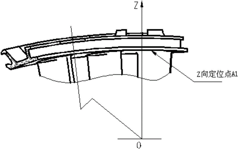
[0024] In the XOZ basic coordinate system, select the test piece, that is, the positioning point of the conjoined guide vane in the direction of the Z coordinate axis. Z-axis direction: On the flow channel surface of the large edge plate of the conjoined blade, select the positioning point A1 close to the direction of the blade basin to limit the degree of freedom of the test piece in the Z-axis direction;

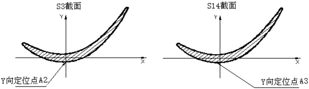
[0025] In the XOY basic coordinate system, select the anchor point of the test piece, that is, the conjoined guide vane in the direction of the Y coordinate axis. It is used to limit the degree of freedom of the test piece in the Y-axis direction; Y-axis direction: select two positioning points A2 and A3 on the outermost blade of the conjoined blade, the blade back of the S3 section and the S14 section, and the selected positions of the two points It needs to ...

Embodiment 2

[0031] Taking the six-unit guide vane as an example, its 7-point positioning method includes the following steps:

[0032] In the XOZ basic coordinate system, select the test piece, that is, the positioning point of the conjoined guide vane in the direction of the Z coordinate axis. Z-axis direction: On the flow channel surface of the large edge plate of the conjoined blade, select the positioning point B1 close to the direction of the blade basin to limit the degree of freedom of the test piece in the Z-axis direction;

[0033] In the XOY basic coordinate system, select the anchor point of the test piece, that is, the conjoined guide vane in the direction of the Y coordinate axis. It is used to limit the degree of freedom of the test piece in the Y-axis direction; Y-axis direction: on the outermost blade of the conjoined blade, two positioning points B2 and B3 are selected for the S4 section and the S15 section, and the selected positions of the two points must be parallel to...


PUM


Abstract

The invention discloses a positioning method for an integrated guide vane. The integrated guide vane generally needs to be installed on a measurement tool or a tool clamp so as to be finished, measured and machined, and the effects that the vane is installed in the most stable state and meanwhile the position of the vane on the measurement tool or the tool clamp is proper are guaranteed by the adoption of the positioning method. The positioning method for the integrated guide vane is characterized by comprising the following steps that the coordinate point in the X-axis direction is selected and set, and four positioning points are set in the X-axis direction. According to a traditional positioning way, three positioning points are selected in the X-axis direction for determining a datum plane, positioning errors are caused due to the fact that the positioning datum in the X-axis direction does not coincide with the designed datum after the vane deforms, the longer the vane is, the larger the deformation is, and consequentially the deviation of the datum plane in the X-axis direction is larger. The positioning method for the integrated guide vane has the advantages that certain positive effects are achieved in the aspect of control over the size and the form and position accuracy of vane castings, the vane casting yield is increased, the model development cycle is shortened, and the development cost is reduced.

Description

technical field [0001] The invention relates to the field of mechanical processing, in particular to a positioning method of conjoined guide blades. Background technique [0002] The reasonable setting of the blade positioning method is the key factor to ensure the dimensional accuracy of the blade. In the space Cartesian coordinate system, a conjoined blade has six possibilities of movement. The traditional positioning method of the conjoined guide vane adopts the principle of six-point positioning to limit the six degrees of freedom of the blade, and at the same time, it can ensure that the blade moves in the most stable position. state installation, measurement and processing. However, the disadvantage of this method is that after the blade is deformed, the positioning datum and the design datum will not coincide, resulting in positioning errors, that is, it cannot ensure that the blade is in the correct position on the measuring tool or fixture, which will cause the bla...

Claims


Application Information

Patent Timeline
Patent Type & Authority Applications(China)
IPC IPC(8): B23Q3/18B25B11/00
Inventor 王丽萍顾欣王永明张松胜刘建平
Owner SHENYANG LIMING AERO-ENGINE GROUP CORPORATION
Why Eureka
Try Eureka