
Cutting machine with adjustable staying duration

A cutting machine and long-term technology, applied in metal processing and other directions, can solve the problems of easy damage, difficult maintenance of electrical control devices, etc., and achieve the effect of convenient adjustment

Inactive Publication Date: 2016-05-18
DINGSHENG CORP
View PDF0 Cites 5 Cited by
  • Summary
  • Abstract
  • Description
  • Claims
  • Application Information

AI Technical Summary

Problems solved by technology

However, the electrical control device is difficult to repair and easy to damage.

Method used


Image

  • Cutting machine with adjustable staying duration

Examples


Embodiment Construction

[0013] The present invention will be described in further detail below by means of specific embodiments:

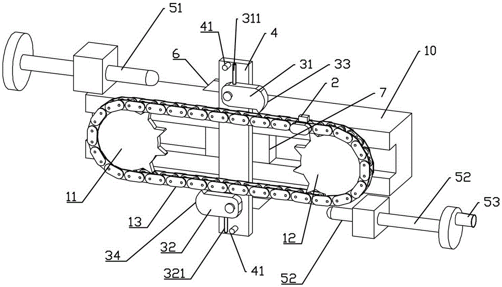
[0014] The reference numerals in the accompanying drawings of the description include: frame 10, driving sprocket 11, driven sprocket 12, transmission chain 13, trigger block 2, slide block 7, driven lever 4, first trigger claw 31, second Trigger pawl 32, first stop lever 51, second stop lever 52, slope 6, first trigger surface 33, second trigger surface 34, first limit lever 41, first swing lever 311, second limit Rod 42 , second swing rod 321 , rotating handle 53 .

[0015] Such as figure 1 The shown cutting machine with adjustable dwell time includes a frame 10, a motor, a transmission mechanism and a cutting knife, wherein the transmission mechanism includes a driving sprocket 11, a driven sprocket 12, a transmission chain 13, a driven mechanism, a second One stop lever 51, the second stop lever 52 and the cutter, the driving sprocket 11 and the driven sprocket 12 a...


PUM


Abstract

The invention relates to a transmission mechanism of a paper cutting device, in particular to a cutting machine with an adjustable staying duration. The cutting machine comprises a rack, a motor, a transmission mechanism and a cutting knife. The transmission mechanism comprises a drive chain wheel, a driven chain wheel, a transmission chain, a driven mechanism, a first stop rod, a second stop rod and a cutter. The drive chain wheel is equal to the driven chain wheel in size. The driven mechanism comprises a sliding block, a driven rod, a first triggering claw and a second triggering claw. The motor is connected with the drive chain wheel. The transmission chain is arranged outside the drive chain wheel and the driven chain wheel in a sleeving manner. A triggering block is fixed to the transmission chain. The invention aims at providing the purely-mechanical cutting device of which the cutting knife can stay for a period of time after primary cutting is finished.

Description

technical field [0001] The invention relates to a transmission mechanism of a paper cutting device, in particular to a cutting machine with adjustable dwell time. Background technique [0002] In the process of printing paper products in batches, it involves the process of cutting paper, and after printing, it also involves the process of trimming and modifying. All of these processes involve cutting with a cutting knife. Commonly used cutting blades are driven by a mechanism such as a crank connecting rod or a four-bar linkage to perform reciprocating cutting. When using the problem that these transmission structures exist, after completing a cutting, if there is no electrical control device, there is no interval in the process of reciprocating cutting. However, the electrical control device has the problems of being difficult to overhaul and easily damaged. Contents of the invention [0003] The present invention intends to provide a purely mechanical cutting device i...

Claims


Application Information

Patent Timeline
Patent Type & Authority Applications(China)
IPC IPC(8): B26D1/06B26D5/08
CPCB26D1/065B26D5/08
Inventor 胡佐林
Owner DINGSHENG CORP
Learn More