Fluid treatment device

A technology of fluid treatment and treatment section, which is applied in the field of continuous reaction devices to ensure the effect of reaction time

Pending Publication Date: 2021-08-06
M TECH CO LTD
View PDF15 Cites 0 Cited by
  • Summary
  • Abstract
  • Description
  • Claims
  • Application Information

AI Technical Summary

Problems solved by technology

Patent Document 5 achieves a homogeneous reaction in the annular flow path by improving the homogeneity of the treated fluid introduced into the annular flow path, and there is no specific description for the further treatment of the fluid discharged from the annular flow path

Method used


Image

  • Fluid treatment device
  • Fluid treatment device
  • Fluid treatment device

Examples


Embodiment Construction

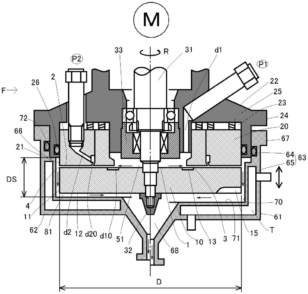
[0068] Embodiments of the present invention will be described below based on the drawings.

[0069] (About Fluid Handling Device F)

[0070] For Fluid Handling Unit F, refer to Figure 1 to Figure 15 Be explained.

[0071] The fluid treatment device F includes an upstream treatment section defined by at least two processing surfaces that rotate relatively and a downstream treatment section arranged downstream of the upstream treatment section. It passes through an upstream processing space defined by at least two processing surfaces, thereby performing upstream processing on the fluid to be processed.

[0072] The fluid processing unit F in the upstream side processing space is the same as the device described in Patent Documents 3-5. Specifically, the fluid to be processed is processed in an upstream processing space defined by at least two processing surfaces that rotate relatively. It is a device that introduces a first fluid, which is the first fluid to be processed, i...


PUM


Abstract

A fluid treatment device with a new configuration is provided. The fluid treatment device F is provided with an upstream treatment unit defined by treatment surfaces 1, 2 that rotate relative to each other, and a downstream treatment unit arranged downstream of the upstream treatment unit. The upstream treatment unit is configured such that, by passing the fluid to be treated into an upstream treatment space 3 defined by the treatment surfaces 1, 2, the fluid to be treated is subjected to upstream treatment. The downstream treatment unit is provided with a downstream treatment space 81 which performs the function of retaining and mixing the fluid to be treated by means of a labyrinth seal. An upstream outlet 4 of the fluid to be treated from the upstream treatment unit opens into the downstream treatment space 81, and the downstream treatment space 81 is configured to use the labyrinth seal to perform the function of controlling retention time. The downstream treatment space 81 is provided with narrow seal spaces 84, and retention spaces 83 arranged upstream of the seal spaces 84 and wider than the seal spaces 84, and the upstream outlet 4 opens to a retention space 83.

Description

technical field [0001] The present invention relates to improvements in fluid treatment devices employing a treatment space defined by at least two treatment surfaces at least one of which rotates relative to the other. More specifically, it relates to a continuous reaction device effective and useful in the fields of chemistry, biochemistry, agriculture, food, medicine, cosmetics, metal industry, etc., especially chemical reaction and synthesis. Background technique [0002] In general, the reaction treatment for obtaining a new substance by chemically reacting two or more kinds of substances or one kind of substance itself is roughly classified into a batch method and a continuous method. In the batch reaction process, a solvent, a substrate, and a reactant are placed in a container such as a flask in a laboratory, and the reaction is performed by stirring with a stirrer or the like. Both the batch type and the continuous type have been put into practical use industrially...

Claims


Application Information

Patent Timeline
Patent Type & Authority Applications(China)
IPC IPC(8): B01J19/18B01F7/26B01F7/28B01F13/00B01F15/06B01J19/00B01J19/12B01F27/93B01F27/94
CPCB01J19/006B01J19/0066B01J19/0073B01J19/126B01J19/1806B01J19/1887B01J2219/00094B01J2219/00141B01J2219/00765B01F27/2712B01F27/2711B01F27/2721B01F27/2722B01F35/92B01J19/20B01J19/0013B01J19/0086B01F27/94B01F27/93B01F33/00B01F35/90B01F2101/2204
Inventor 榎村真一
Owner M TECH CO LTD
Why Eureka
Try Eureka