
Circular screen head of circular screen printer

A rotary screen printing and rotary screen technology, applied in the field of rotary screen head, can solve the problems of affecting the running speed of the production line, poor control of precision, and low production efficiency, so as to achieve good control of screen printing paste effect and convenient adjustment of tension of the screen , Ingenious design effect

Inactive Publication Date: 2016-05-18
SUZHOU RUIRI TEXTILE SCI & TECH
View PDF5 Cites 2 Cited by
  • Summary
  • Abstract
  • Description
  • Claims
  • Application Information

AI Technical Summary

Problems solved by technology

[0003] At present, due to the lack of design of the rotary screen mechanism of the existing rotary screen printing machine, there are generally disadvantages such as complex structure, inconvenient adjustment and use, poor control of precision, low work efficiency, high failure rate, and high maintenance costs, which affect the entire production line. The operating speed is low, the production efficiency is low, and the rotary screen head usually uses a guide shaft and a spring structure to fix the screen head bearing seat, the screen head bearing seat is connected to the screen head bushing through the rotary screen bearing, and the rotary screen is installed on the screen head bushing
The rotary screen head of this structure must move the screen head seat of the rotary screen head with the help of peripheral mechanisms to stretch the net, and the tension of the spring will decrease after long-term use, resulting in the tension of the rotary net. When the rotary screen head is adjusted horizontally, it is necessary to move the screen head seat and the rotary screen as a whole, which makes the horizontal adjustment structure complicated and the accuracy difficult to control

Method used


Image

  • Circular screen head of circular screen printer
  • Circular screen head of circular screen printer
  • Circular screen head of circular screen printer

Examples


Embodiment Construction

[0018] In order to make the technical means, creative features, objectives and effects of the present invention easy to understand, the present invention will be further described below in conjunction with specific embodiments.

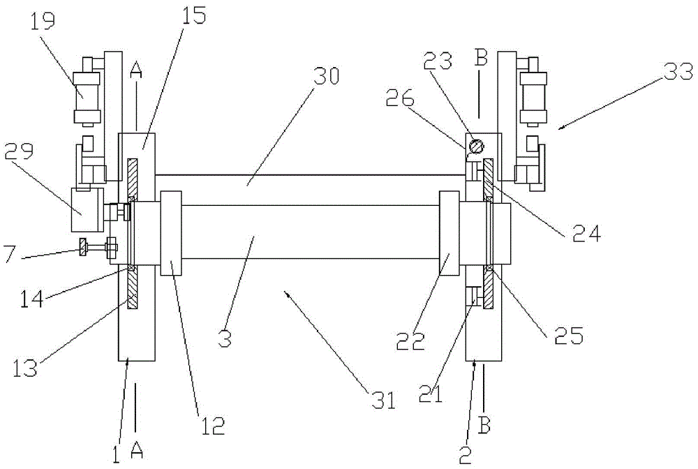
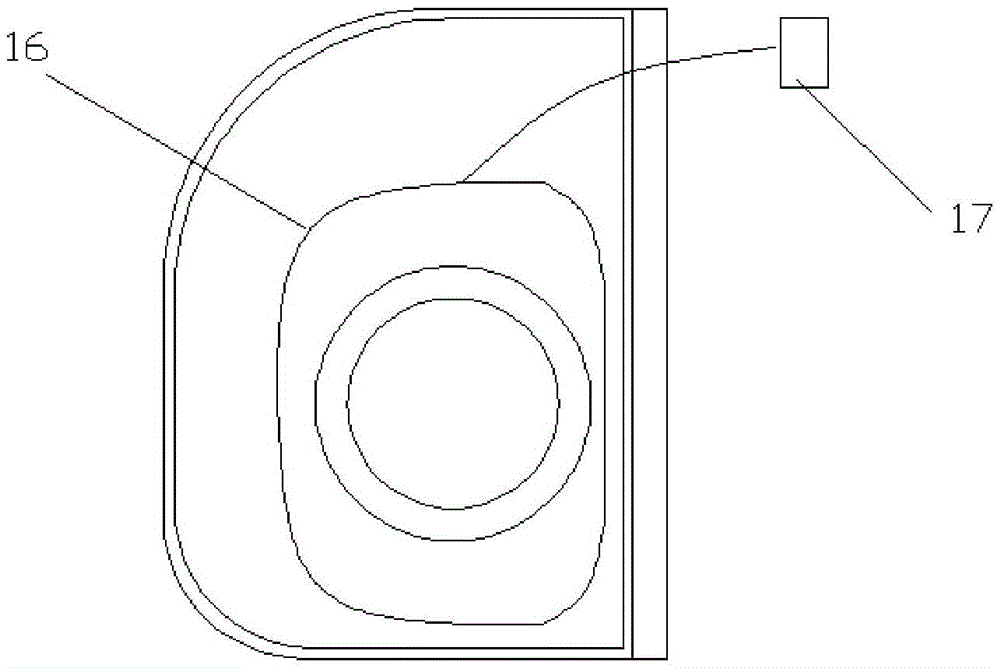
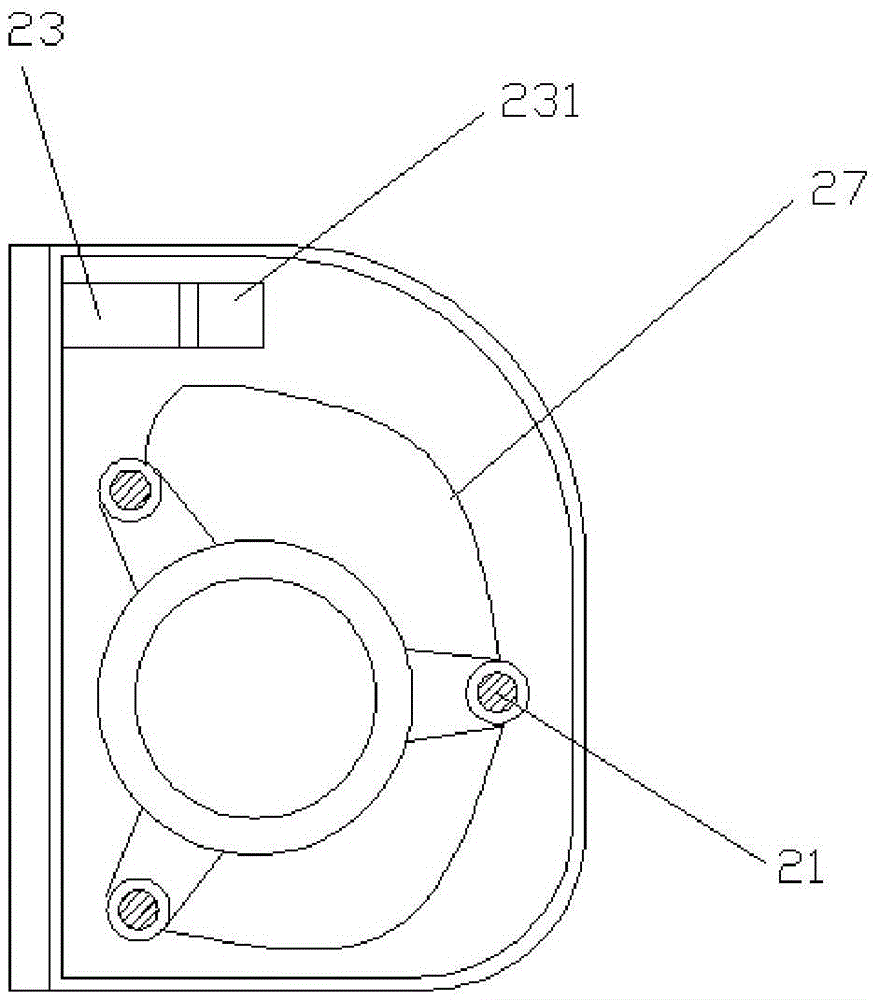
[0019] Such as Figure 1 to Figure 4 The rotary screen head of a rotary screen printing machine shown includes a rotary screen 3, a transmission side rotary screen head 1 and a pump side rotary screen head 2, and is characterized in that the pump side rotary screen head 2 is provided with More than two oil cylinders 21, a pump side net head bearing seat 24, a pump side net head bushing 22 and an oil injection cylinder 23 connected with each oil cylinder, the telescopic ends of each oil cylinder are connected with the pump side net head bearing seat, and the pump side The screen head bearing seat is connected with the pump side screen head bushing through the matching cylinder bearing, the expansion and contraction direction of each oil cylinder 21 is ...


PUM


Abstract

The invention discloses a circular screen head of a circular screen printer. The circular screen head comprises a circular screen, a transmission side circular screen head body and a pump side circular screen head body. Two or more oil cylinders, a pump side screen head bearing seat, a pump side screen heat shaft bushing and an injecting oil cylinder connected with all the oil cylinders are arranged in the pump side circular screen head body. The telescopic ends of all the oil cylinders are connected with the pump side screen head bearing seat. The pump side screen head bearing seat is connected with the pump side screen head shaft bushing through a matched circular screen bearing. The telescoping direction of all the oil cylinders is parallel to the axis of the circular screen. The pump side screen head shaft busing is connected with the other end of the circular screen and is coaxial with the circular screen. The moving direction of the pump side screen head shaft bushing is consistent with the axial direction of the circular screen. The circular screen head has the advantages of being simple in structure, reasonable, ingenious in design, easier to control and the like.

Description

Technical field: [0001] The invention belongs to the technical field of textile machinery, and in particular relates to a rotary screen head of a rotary screen printing machine. Background technique: [0002] The rotary screen printing machine used in textile mills is a screen printing machine that uses a continuously rotating seamless cylindrical screen for printing. The rotary screen printing machine is used in combination with other units. It can be used for printing cotton fabrics, chemical fibers and their blended fabrics, general knitted fabrics, and silk fabrics. The applicable raw materials are: nylon multifilament (thread), polypropylene filament ( yarn), polypropylene, polyester, nylon, PP, low elastic, high elastic, cotton yarn (thread), pearl yarn, leather, mixed, etc. The rotary screen printing machine has reasonable structure, easy operation and high production efficiency, so it is widely used in the field of textile production. [0003] At present, due to th...

Claims


Application Information

Patent Timeline
Patent Type & Authority Applications(China)
IPC IPC(8): B41F15/38B41F15/14
CPCB41F15/14B41F15/38
Inventor 钱彩华
Owner SUZHOU RUIRI TEXTILE SCI & TECH
Learn More