
Multi-head automatic printing machine

A printer and automatic technology, applied in printing, stamping, etc., can solve problems such as slow processing speed, inconvenient adjustment, structural defects, etc., and achieve the effects of fast conversion speed, convenient operation, and improved production efficiency

Active Publication Date: 2016-05-18
ZHENYI ELECTRONICS SHENZHEN
View PDF14 Cites 2 Cited by
  • Summary
  • Abstract
  • Description
  • Claims
  • Application Information

AI Technical Summary

Problems solved by technology

However, this technology has structural defects, such as slow processing speed and inconvenient adjustment.

Method used


Image

  • Multi-head automatic printing machine
  • Multi-head automatic printing machine
  • Multi-head automatic printing machine

Examples


Embodiment Construction

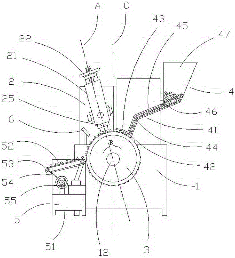
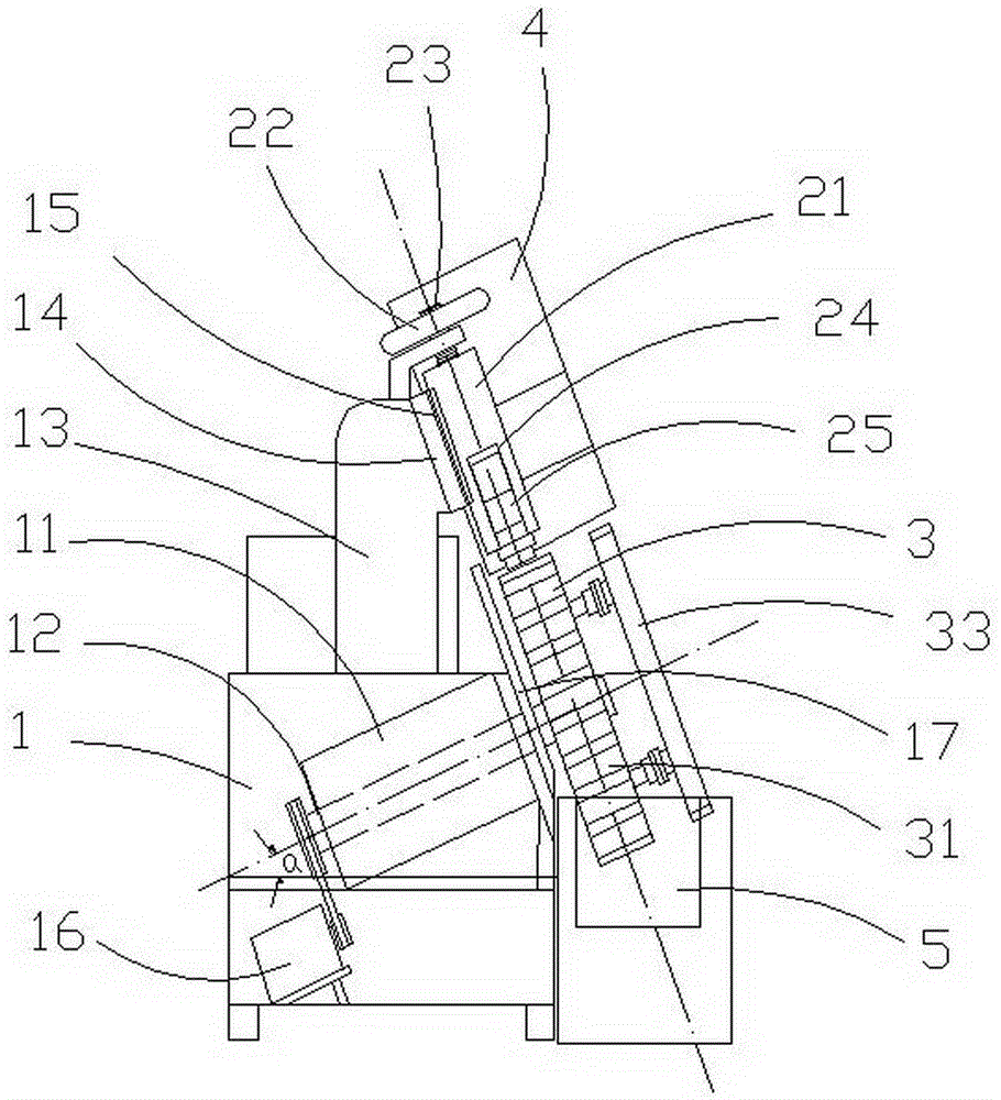
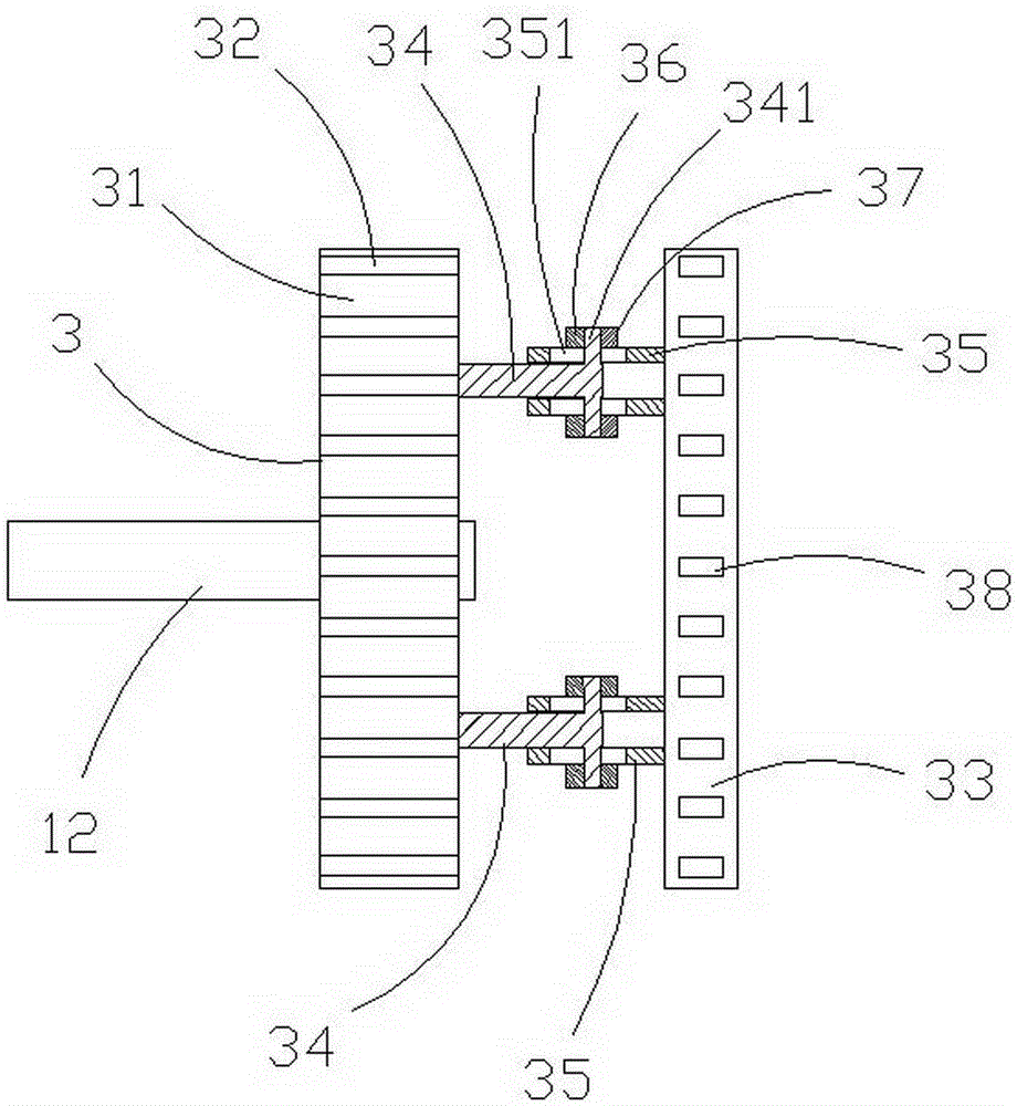
[0021] like figure 1 , 2 , 3, shown in 6, a kind of multi-head automatic printer, comprises frame 1, printing mechanism 2, feeding turntable 3, input mechanism 4, output mechanism 5, frame 1 side fixed spindle box 11, and spindle box 11 is obliquely equipped with Form the main shaft 12 of 30 ° angle α with the plane of the fuselage, and the main shaft 12 is driven by the variable speed motor 16 to rotate. The feed turntable 3 is connected to the main shaft 12 to form an inclined shape. A baffle plate 17 that can axially adjust the printing part of the circular workpiece is arranged between the headstock 11 and the feed turntable 3 . The outer side of the feed turntable 3 is connected to a support ring 33 . When the circular workpiece enters the rolling groove 31 of the feeding turntable 3, one end of the circular workpiece automatically slides to the baffle plate 17, so that the printing part of the circular workpiece is uniformly positioned. According to the printing positio...


PUM


Abstract

The invention discloses a multi-head automatic printing machine. A main shaft is installed in a main shaft box in a machine frame of the printing machine in an inclined mode, the included angle between the main shaft and the plane of a machine body is 30 degrees, a feeding rotation plate is connected to the main shaft in a tipping mode, and locating guide columns on the outer side of the feeding rotation plate are connected to threaded sleeves on a supporting ring in a sleeved mode; a supporting column of a printing mechanism is fixed in a guide rail of a base plate through a pressing plate and a bolt, a screw on the top of the supporting column is provided with an adjusting hand wheel, and a cross-shaped die head is loosely connected in an open groove in the lower end of the supporting column and is provided with four unit matrix control parts containing matrixes; an arc-shaped baffle covering a rolling groove in a suspended mode is arranged at an outlet end of a feeding rack of an inputting mechanism, an arc-shaped stop frame is arranged on the back of a bent material way, and a feed divider is arranged at the lower end port of a hopper; an inclined feeding belt is arranged at the upper part of a support base of an outputting mechanism, the two branch ends of a driven shaft at the other end of the feeding belt are connected with poke rods, and the hand wheel adjusts ascent or descent of the feeding belt.

Description

technical field [0001] The invention relates to a device for printing on the surface of a workpiece, in particular to a multi-head automatic printer. Background technique [0002] The specifications, trademarks, codes and other markings on the surface of the drill bit are currently stamped by hand. This method is labor-intensive, low in efficiency, and the fonts are of different depths, which affects the visual aesthetics and quality of the product. Someone once invented a cylindrical workpiece coding machine (notification number CN100546835). The fuselage of this machine has a built-in motor and a gearbox, and an adjustable bracket is installed obliquely on the fuselage. The width-adjustable hopper is mounted on the adjustable bracket. The width-adjustable hopper is connected to the curved material channel, and the front end of the width-adjustable hopper is equipped with a material shifting mechanism. The main shaft box is fixed in front of the fuselage. The main shaft box...

Claims


Application Information

Patent Timeline
IPC IPC(8): B41K3/02B41K3/36B41K3/44
CPCB41K3/02B41K3/36B41K3/44
Inventor 叶亚男
Owner ZHENYI ELECTRONICS SHENZHEN
Learn More