Self-adjustable pipeline rectification device

A rectification device and self-adjusting technology, applied in the direction of fluid flow, mechanical equipment, etc., can solve the problems of not improving the flow stability of the downstream pipeline, not being able to adjust the flow performance well, and affecting the transmission volume of the flow medium in the pipe, etc., to achieve Ease of maintenance and operation, elimination of vibration phenomenon, effects of rectifying fluid flow performance

Inactive Publication Date: 2017-08-29
LANZHOU UNIVERSITY OF TECHNOLOGY
View PDF5 Cites 0 Cited by
  • Summary
  • Abstract
  • Description
  • Claims
  • Application Information

AI Technical Summary

Problems solved by technology

[0002] In the prior art, turbulence occurs due to the increase of the flow velocity of the transmission medium inside the pipeline. As the turbulence intensifies, the pipeline and equipment will vibrate accordingly, and it will also affect the downstream pipeline network and equipment.
Severe turbulent flow inside the pipeline will not only cause a lot of energy loss, but also adversely affect the safe operation of pipelines and equipment
In addition, the severe turbulent flow will also increase the local resistance of the flow, resulting in a blocked flow effect and affecting the transmission volume of the flowing medium in the pipe.
The existing method of pipeline rectification mainly adopts adding flat plates parallel to the flow direction inside the pipeline, or deflectors or spiral plates at a certain angle with the flow direction, but simply adding flat plates parallel to the flow direction, due to the large gap between the plates, It does not play a good role in adjusting the flow performance; the deflector or spiral plate at a certain angle with the flow direction can adjust the flow state in the pipe to a certain extent, so that the fluid spiral flows forward, but it will cause a large flow resistance , leading to more energy loss, and the resulting helical flow will cause more severe turbulence downstream, which cannot improve the flow stability in the downstream pipeline

Method used


Image

  • Self-adjustable pipeline rectification device
  • Self-adjustable pipeline rectification device
  • Self-adjustable pipeline rectification device

Examples


Embodiment Construction

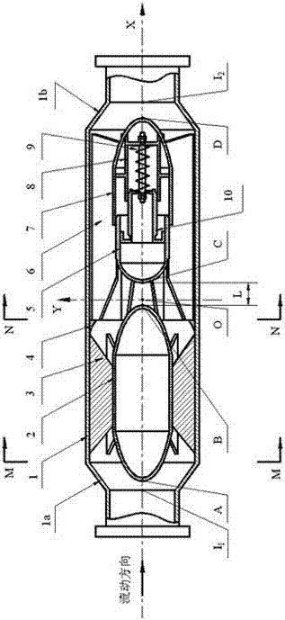
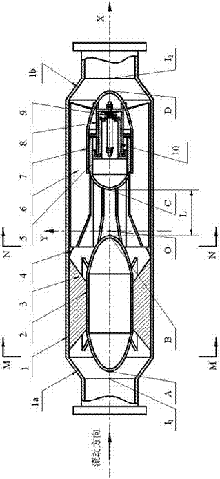
[0007] Such as figure 1 As shown, the self-adjustable pipeline rectification device of the present invention includes a rectification device cylinder body 1, and a rectification device inlet diameter expansion section 1a and a rectification device outlet diameter reduction section 1b, along the medium flow direction from front to rear, the rectification device cylinder The front rectifier body 2 and the rear rectifier body 7 are installed inside the body 1, and the front deflector 3 arranged evenly in the circumferential direction of the front rectifier body 2 is welded on the inner wall of the rectification device cylinder 1 and the outer wall surface of the front rectifier body 2, and the front rectifier body The rectifier body 2 is fixed inside the cylinder body 1 of the rectifier device, the guide ring 4 is installed behind the front guide plate 3, the rear rectifier body 7 is installed in the downstream direction of the guide ring 4, and the rear guide body is evenly arran...


PUM


Abstract

The invention discloses a self-adjustable pipeline rectifying device. A front rectifying body (2) and a rear rectifying body (7) are mounted in a rectifying device barrel (1) in the medium flowing direction from front to back. Front guide plates (3) evenly arranged in the circumferential direction of the front rectifying body (2) are welded to the inner wall of the rectifying device barrel (1) and the outer wall face of the front rectifying body (2), and the front rectifying body (2) is fixed in the rectifying device barrel (1). A guide ring (4) is mounted behind the front guide plates (3). The rear rectifying body (7) is mounted in the downstream direction of the guide ring (4). Rear guide plates (6) evenly arranged in the circumferential direction of the rear rectifying body (7) are welded to the inner wall of the rectifying device barrel (1) and the outer wall face of the rear rectifying body (7), and the rear rectifying body (7) is fixed in the rectifying device barrel (1). A self-adjusting guide cover (5) is mounted on the rear rectifying body (7). A fixed supporting frame (8) is mounted in the rear rectifying body (7). A sliding supporting frame (10) is mounted in the self-adjusting guide cover (5).

Description

technical field [0001] The invention relates to the technical field of valve pipe fittings. Background technique [0002] In the prior art, turbulence occurs due to the increase of the flow velocity of the transmission medium inside the pipeline. As the turbulence intensifies, the pipeline and equipment will vibrate accordingly, and the downstream pipeline network and equipment will also be affected. Severe turbulence inside the pipeline will not only cause a lot of energy loss, but also adversely affect the safe operation of pipelines and equipment. In addition, the severe turbulent flow will also increase the local resistance of the flow, resulting in a blocked flow effect and affecting the transmission volume of the flowing medium in the pipe. The existing method of pipeline rectification mainly adopts adding flat plates parallel to the flow direction inside the pipeline, or deflectors or spiral plates at a certain angle with the flow direction, but simply adding flat pl...

Claims


Application Information

Patent Timeline
Patent Type & Authority Patents(China)
IPC IPC(8): F15D1/02
CPCF15D1/02
Inventor 余龙俞树荣
Owner LANZHOU UNIVERSITY OF TECHNOLOGY
Why Eureka
Try Eureka