Device used with the air induction tube of an internal combustion engine after the air filter and before the throttle body

Active Publication Date: 2018-06-12
RINGELSTETTER ALLEN FRANCIS
View PDF10 Cites 0 Cited by
  • Summary
  • Abstract
  • Description
  • Claims
  • Application Information

AI Technical Summary

Benefits of technology

[0007]According to one advantage of the present invention, the air can be divided into four separate and distinct air flow segments. This advantageously allows the air to be more laminar (less turbulent) immediately before the throttle body which allows a greater amount of air to pass through the throttle body. Air also passes through the throttle body with less restriction allowing the engine cylinders to receive a greater charge of air.
[0008]The increased charge of air increases the torque range of the engine, increases horsepower, improves engine efficiency and eliminates a low end lag in acceleration. It is important to note that these benefits of increased charge are achieved even with a normally aspirated engine (i.e. even without turbo or super charging). In a dyno test of the illustrated embodiment of the present invention used within a 3-inch a

Problems solved by technology

Turbulence in the air flow before the throttle body results in less than optimal air flow throug

Method used


Image

  • Device used with the air induction tube of an internal combustion engine after the air filter and before the throttle body
  • Device used with the air induction tube of an internal combustion engine after the air filter and before the throttle body
  • Device used with the air induction tube of an internal combustion engine after the air filter and before the throttle body

Examples


Example

[0024]While the invention will be described in connection with one or more preferred embodiments, it will be understood that it is not intended to limit the invention to those embodiments. On the contrary, it is intended to cover all alternatives, modifications and equivalents as may be included within the spirit and scope of the invention as defined by the appended claims.

[0025]Most air induction tubes 10 range from 1-6 inches in diameter. For sake of example, a 3-inch tube will be illustrated. The tube 10 has an inside 11 with a perimeter wall 12 that has a generally circular profile. The tube 10 has two opposed ends 13 and 14.

[0026]An air filter box 20 is at one end 13 of the air induction tube 10 and a throttle body 30 is at the opposite end 14 of the induction tube 10. The throttle body 30 controls the amount of air that enters the engine.

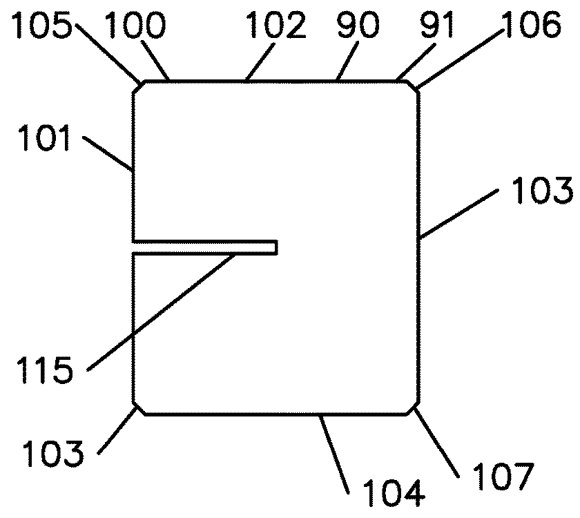
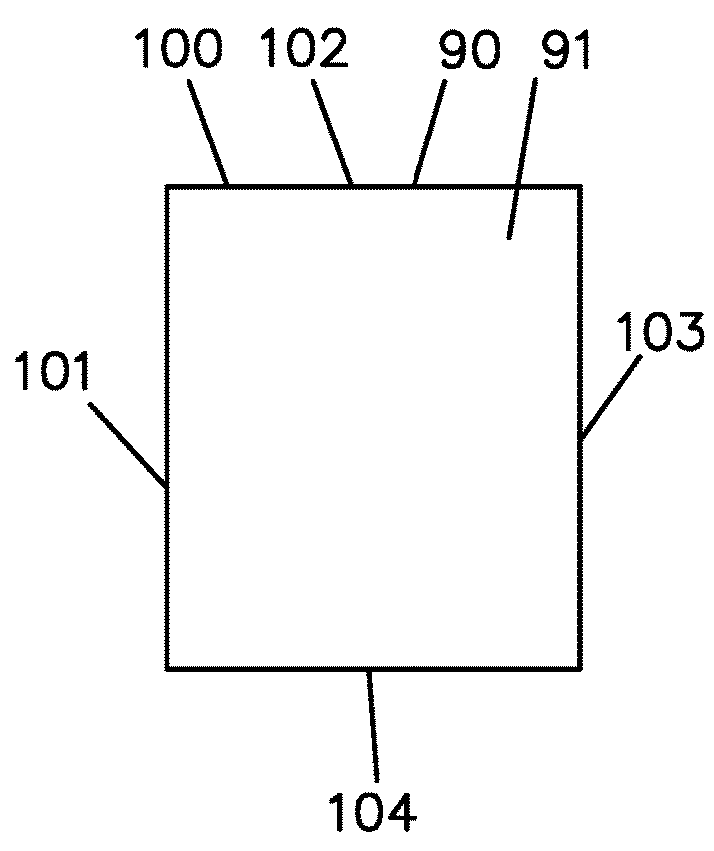
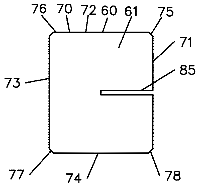
[0027]The device 50 is formed from two pieces 60 and 90, respectively. A blank unformed stock that will become piece 60 is illustrated in FIG...


PUM


Abstract

Provided is a device used in the air induction tube of an internal combustion engine after the air filter and before the throttle body, and in particular to a device used to separate an air flow into a plurality of segments. The device can be made of two pieces. Each piece is initially a flat plate. A slit is formed half way through each plate and the corners are cut off or clipped. Each plate is then formed to have two generally curved portions. The pieces are joined via the slits resulting in the device. The pieces are generally perpendicular to each other at their intersection. The device is fitted into the air induction tube upstream of the throttle body, whereby it separates the air flow into distinct segments. The curved walls can be slightly compressed when inserted into an induction tube to hold the assembly in place.

Description

[0001]This United States utility patent application claims priority on and the benefit of provisional application 62 / 183,892 filed Jun. 24, 2015, the entire contents of which are hereby incorporated herein by reference.BACKGROUND OF THE INVENTION1. Field of the Invention[0002]The present invention relates to a device used with the air induction tube of an internal combustion engine after the air filter and before the throttle body, and in particular to a device used to separate an air flow into a plurality of segments.2. Description of the Related Art[0003]Engines can have an air filter that to filter air before it enters a combustion chamber of the engine. The air filter is typically held in a box (or housing) and is upstream of a throttle body. The throttle body regulates how much air can enter the combustion chamber through an intake manifold and contains a valve. An air induction tube is generally located between the air filter box and the throttle body.[0004]Turbulence in the a...

Claims


Application Information

Patent Timeline
IPC IPC(8): F02M35/10
CPCF02M35/10262F02M35/10367F02M35/10124Y02T10/12
Inventor RINGELSTETTER, ALLEN FRANCIS
Owner RINGELSTETTER ALLEN FRANCIS
Why Eureka
Try Eureka