Optical fiber distributed sensing system of U-type sensing fiber deployment structure

A technology of optical fiber distribution and sensing optical fiber, which is applied in the field of optical fiber optics, information acquisition and perception, and optical engineering. It can solve the problem of the minimum integration time limiting the spatial resolution, etc., and achieve the effect of high-resolution positioning and speed measurement

Active Publication Date: 2016-05-18
UNIV OF ELECTRONICS SCI & TECH OF CHINA
View PDF9 Cites 10 Cited by
  • Summary
  • Abstract
  • Description
  • Claims
  • Application Information

AI Technical Summary

Problems solved by technology

However, the pulse width of the incident laser and the minimum integration ti...

Method used


Image

  • Optical fiber distributed sensing system of U-type sensing fiber deployment structure
  • Optical fiber distributed sensing system of U-type sensing fiber deployment structure
  • Optical fiber distributed sensing system of U-type sensing fiber deployment structure

Examples


Embodiment 1

[0028] Optical fiber distributed sensing system based on single U-shaped optical fiber distribution structure

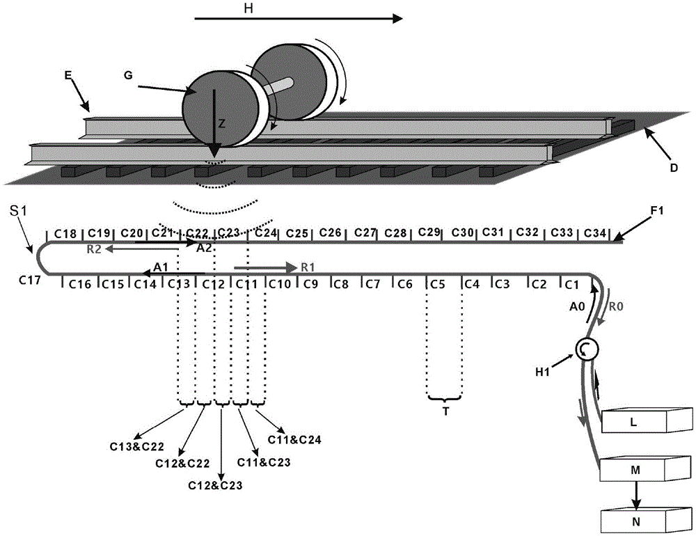
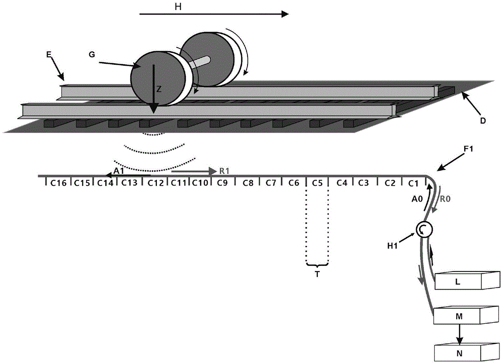
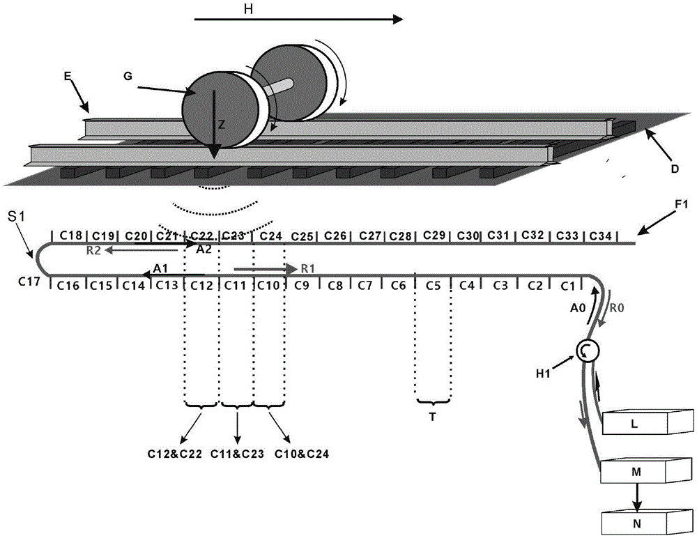
[0029] figure 1Demonstrated an optical fiber distributed sensing system based on a single U-shaped sensing optical fiber distribution structure, a single U-shaped optical fiber F1 is buried shallowly in the soil below the surface along the track, parallel to the train track and kept 20cm to the train track The linear distance of 30cm ensures that the sensing fiber maintains high sensitivity to vibration. The vibration signal (Z) generated by the movement of the locomotive on the track will act indirectly on the sensing fiber to change the transmission and scattering characteristics of the sensing fiber. According to the pulse width (T) of the pulsed laser used in the system, the sensing fiber is sequentially divided into continuous channels (C1, C2, C3...C34) with a length of (T / 2) from the laser incident end, and the incident pulsed laser A0, A1 passes through the...

Embodiment 2

[0042] Optical Fiber Distributed Sensing System Based on 3U Optical Fiber Distribution Structure

[0043] Such as Figure 5 As shown, on the basis of the above-mentioned single U interleaved distribution structure, a 3U optical fiber distribution structure can be further adopted, in which the corresponding channels have a dislocation of 1 / 4 channel length. 5-A is the vibration signal (Z) waveform generated by the wheel during motion, and 5-B is the backscattered light signal sampled by channels C55, C56, C57, C58, C59, and C60 when the light pulse is transmitted in the optical fiber Waveform, 5-C is the backscattered light signal waveform sampled by channels C49, C48, C47, C46, ​​C45, and C44 when the optical pulse is transmitted in the optical fiber, 5-D is the channel C21 when the optical pulse is transmitted in the optical fiber , C22, C23, C24, and C25 sampled backscattered light signal waveforms, 5-E is the backscattered light signal waveform sampled by channels C13, C12...


PUM


Abstract

The invention relates to the field of optical engineering, optical fiber optics and sensing techniques and particularly relates to an optical fiber distributed sensing system of a U-type sensing fiber deployment structure. According to the technical scheme of the invention, a sensing fiber arranged in the optical fiber distributed sensing system and used for detecting a vibration signal is set to be of a multi-U-type structure. The multi-U-type structure comprises N-1 U shapes formed by N parallel edges, wherein adjacent U shapes are different in direction and N is larger than 1. From the initiating end of the sensing fiber, the sensing fiber is successively divided into a series of continuous and isometric channels. The length of each channel is one half the line width T of an incident pulse laser. Each channel on one parallel edge of the sensing fiber is not overlapped with the corresponding channels on the adjacent parallel edges of the sensing fiber in a direction vertical to the parallel edges of the sensing fiber. On the premise that the pulse width and the incident power of a light source and the minimum integration time of a photoelectric detector are not reduced at all, the spatial resolution of the system is improved.

Description

technical field [0001] The invention relates to the technical fields of optical engineering, optical fiber optics, and information acquisition and perception, in particular to optical fiber sensing and signal processing technologies. Background technique [0002] With the rapid development of rail transit such as high-speed railways and urban subways in my country and other countries in the world, the increasing number of rail lines and locomotives makes the criss-crossing rail traffic increasingly busy. As well as accurate speed measurement and other aspects put forward higher requirements. In view of such a situation, traditional electrical sensors can no longer meet the needs in many places with strong electromagnetic interference, and there are great hidden dangers in their reliability and safety. [0003] Optical fiber distributed sensor is a distributed stress sensing system based on optical time domain reflectometry (OTDR). This technology is due to the limitation of...

Claims


Application Information

Patent Timeline
IPC IPC(8): G01D5/26
CPCG01D5/268
Inventor 宋情吴宇彭飞饶云江
Owner UNIV OF ELECTRONICS SCI & TECH OF CHINA
Why Eureka
Try Eureka