Counting transmission wheel train for gas meter counter

A transmission wheel train and counter technology, applied to instruments, volume metering, measuring devices, etc., can solve the problems of inflexible rotation, increase the serial movement of driven exchange gears, and reduce the adjustment efficiency, so as to improve the counting accuracy and The effect of adjusting efficiency, reducing the amount of matching deformation, and high motion precision

Inactive Publication Date:
View PDF10 Cites 5 Cited by
  • Summary
  • Abstract
  • Description
  • Claims
  • Application Information

AI Technical Summary

Problems solved by technology

This will lead to severe deformation of the matching hole between the driven transition gear and the support shaft in the gear set, resulting in inflexible rotation or stagnation, etc., which will affect the normal operation of the counter, or the setting of the axial limit structure will lead to the need to remove more components during adjustment. And reduce the adjustment efficiency, and the manufacturing and assembly process is very poor
In addition, the driven exchange gear and the worm shaft must be separated, which increases the serial movement of the driven exchange gear and occupies too much limited space
In addition, the existing gear train and the counting digital wheel are connected by gear transmission, and the counting value can be implemented by directly rotating the counting digital wheel, so there is a hidden danger of artificial adjustment

Method used


Image

  • Counting transmission wheel train for gas meter counter
  • Counting transmission wheel train for gas meter counter
  • Counting transmission wheel train for gas meter counter

Examples


Embodiment Construction

[0020] The present invention will be further described below in conjunction with the accompanying drawings, but the present invention is not limited to the scope of the described embodiments.

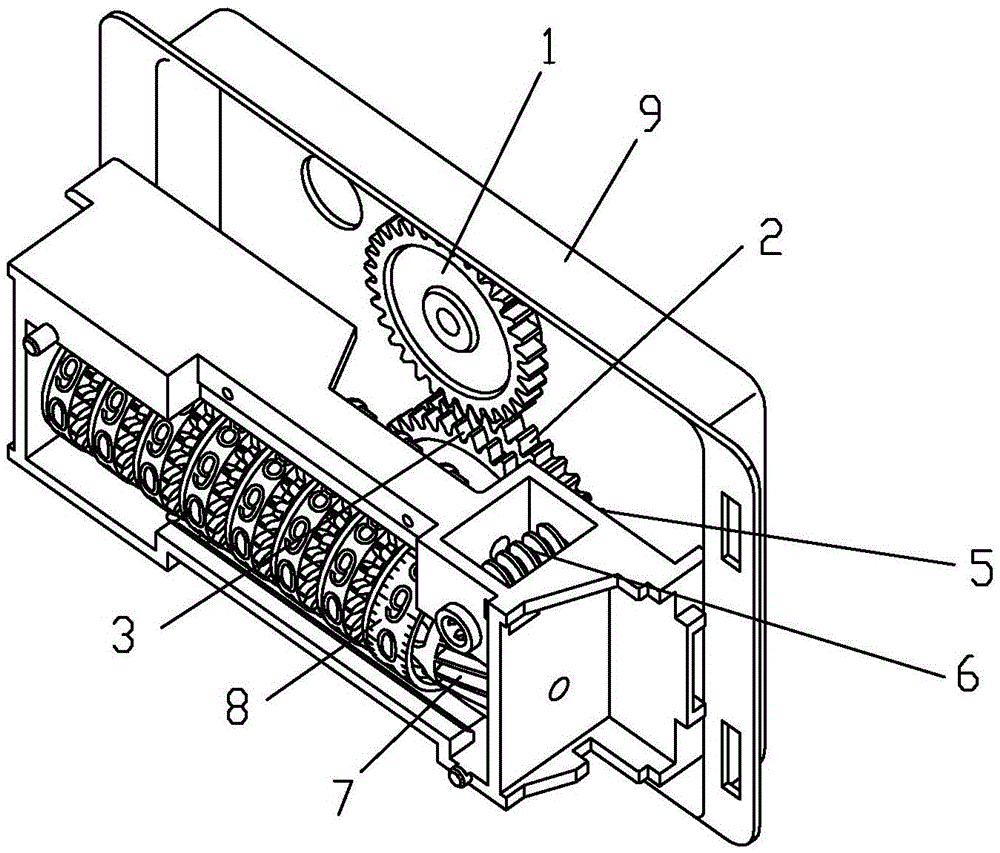
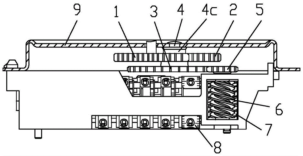
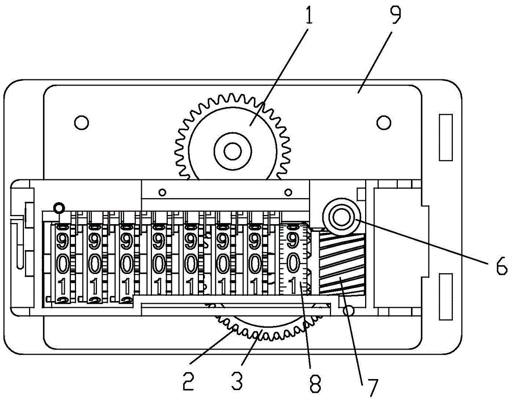
[0021] see figure 1 , figure 2 , image 3 , Figure 4 , Figure 5 , Image 6 , Figure 7 , Figure 8 , a counting transmission gear train for a gas meter counter, including a pair of exchange gears and a transition gear pair, the active exchange gear 1 of the exchange gear pair constitutes the input end of the gear train, and the driven exchange gear 2 of the exchange gear pair passes through the transition gear The convex ring section 3a formed in the middle of the active transition gear 3 is tightly fitted on the active transition gear 3, and the driven exchange gear 2 forms a coaxial fixed connection through the active transition gear 3, and the two are rotatable through the inner hole of the active transition gear 3 Fitted on the support shaft 4, the driven exchange gear 2 i...


PUM


Abstract

The invention discloses a counting transmission wheel train for a gas meter counter. The counting transmission wheel train comprises a change gear pair and a transition gear pair. A driving change gear forms the input end of the wheel train, and a driven change gear is in tight fit with a driving transition gear through a protruding ring section formed in the middle of the driving transition gear of the transition gear pair. The driven change gear and the driving transition gear are coaxially connected and are arranged on a supporting shaft in a running fit mode through an inner hole in the driving transition gear. The driven change gear and the driving transition gear are located on the inner section and the outer section of the supporting shaft respectively. A shaft shoulder for axial limiting of the driven change gear is formed on the inner side of the fit section of the supporting shaft. A protruding shoulder for preventing exiting of the driving transition gear is formed at the far end of the fit section of the supporting shaft. A driven transition gear is coaxially and fixedly connected with a worm. A worm wheel meshed with the worm is coaxially and fixedly connected with a first character wheel of a counting character wheel set. The counting transmission wheel train has the advantages that the structure is simple, the counting wheel train movement precision is high, counting of the counter is accurate, and the hidden danger that the counting number is manually adjusted is avoided.

Description

technical field [0001] The patent of the present invention relates to a gas meter counter component, in particular to a counting drive train for a gas meter counter. Background technique [0002] The measurement of the gas consumption is realized by the gas meter. The core of the gas meter includes a movement and a counter. For the mechanical counter, the movement outputs the measurement results, and the mechanical counter realizes the cumulative display of the gas consumption. The gear transmission system of the counter is the link between the output of the movement and the display wheel. It is usually equipped with an exchange gear and a transition gear. The transition gear is used to match the movement volume of the movement with the counter; the exchange gear is used for the error accuracy of the gas indication value. The adjustment of the gas meter is achieved by selecting different gear ratios. The transition gear is fixed for a gas meter of a certain model and speci...

Claims


Application Information

Patent Timeline
Patent Type & Authority Applications(China)
IPC IPC(8): G01F15/07
CPCG01F15/07
Inventor 王群张敬鎕赵小波
Why Eureka
Try Eureka