Supercharge Your Innovation With Domain-Expert AI Agents!

Antenna device and three-dimensional radar system

An antenna device, three-dimensional radar technology, applied in radar-related fields, can solve the problems of high cost and low reliability of radar systems, and achieve the effects of improving reliability and reducing production costs

Active Publication Date: 2016-05-18
西安象德信息技术有限公司
View PDF6 Cites 10 Cited by
  • Summary
  • Abstract
  • Description
  • Claims
  • Application Information

AI Technical Summary

Problems solved by technology

[0007] The purpose of the present invention is to provide an antenna device and a three-dimensional radar system to solve the technical problems of low reliability and high cost of existing radar systems

Method used


Image

  • Antenna device and three-dimensional radar system
  • Antenna device and three-dimensional radar system
  • Antenna device and three-dimensional radar system

Examples


Embodiment Construction

[0040] The following descriptions of the various embodiments refer to the accompanying drawings to illustrate specific embodiments in which the present invention can be practiced. The directional terms mentioned in the present invention, such as "up", "down", "front", "back", "left", "right", "inside", "outside", "side", etc., are for reference only The orientation of the attached schema. Therefore, the directional terms used are used to illustrate and understand the present invention, but not to limit the present invention. In the figures, structurally similar units are denoted by the same reference numerals.

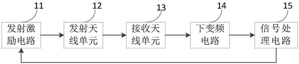
[0041] Please refer to figure 1 , figure 1 It is a structural schematic diagram of the three-dimensional radar system of the present invention.

[0042] Such as figure 1 As shown, the three-dimensional radar system of the present invention includes: a transmitting excitation circuit 11, at least one transmitting antenna unit 12, a receiving antenna unit 13, a down...


PUM


Abstract

The invention provides an antenna device and a three-dimensional radar system. The antenna device comprises at least one emission antenna unit which comprises at least two emission antennas and is used for emitting detection signals to a target to be detected, wherein the emission antennas have a phase center, and the phase center of the emission antennas is distributed in the vertical direction; a receiving antenna unit which comprises at least receiving antennas and is used for receiving reflection signals of the target to be detected, wherein the receiving antennas has a phase center, and the phase center of the receiving antennas is distributed in the horizontal direction. According to the invention, an existing emission antenna is improved, so that the measurement of a pitch angle is realized without adding the receiving antennas, and the three-dimensional position of the target in the space is obtained on the basis that an azimuth angle and the distance of the target are obtained; in addition, the production cost is lowered, and the reliability of the radar system is improved.

Description

technical field [0001] The invention relates to the technical field of radar, in particular to an antenna device and a three-dimensional radar system. Background technique [0002] In the large airspace ground surveillance radar system, it is generally required that the radar system has high azimuth angle resolution and elevation angle measurement capability. The existing radar system generally adopts the following two systems: [0003] The azimuth mechanical scanning system usually uses a narrow beam in the azimuth direction of the antenna, and a wide beam in the elevation direction. The antenna has two receiving channels in the elevation direction under the receiving state, and the elevation angle measurement is realized by using a ratio-amplitude or phase-ratio single pulse. Scanning realizes azimuth and angle measurement. [0004] The azimuth electronic scanning system generally adopts separate antennas for transmitting and receiving. There is only one transmitting ant...

Claims


Application Information

Patent Timeline
IPC IPC(8): G01S7/03G01S13/88
CPCG01S7/03G01S13/88
Inventor 宋春丽
Owner 西安象德信息技术有限公司
Features
  • R&D
  • Intellectual Property
  • Life Sciences
  • Materials
  • Tech Scout
  • Unparalleled Data Quality
  • Higher Quality Content
  • 60% Fewer Hallucinations
Learn More