
Controller protection circuit

A protection circuit and controller technology, applied in emergency protection circuit devices, emergency protection circuit devices used to limit overcurrent/overvoltage, circuit devices, etc., can solve problems such as controller interference, improve work stability, Addressing effects that are susceptible to interference

Active Publication Date: 2016-05-18
PETROCHINA CO LTD
View PDF6 Cites 0 Cited by
  • Summary
  • Abstract
  • Description
  • Claims
  • Application Information

AI Technical Summary

Problems solved by technology

[0006] The present invention provides a protection circuit for a controller to at least solve the technical problem that the controller is susceptible to interference in the prior art

Method used


Image

  • Controller protection circuit
  • Controller protection circuit

Examples


Embodiment Construction

[0023] In order to enable those skilled in the art to better understand the solutions of the present invention, the following will clearly and completely describe the technical solutions in the embodiments of the present invention in conjunction with the drawings in the embodiments of the present invention. Obviously, the described embodiments are only It is an embodiment of a part of the present invention, but not all embodiments. Based on the embodiments of the present invention, all other embodiments obtained by persons of ordinary skill in the art without making creative efforts shall fall within the protection scope of the present invention.

[0024] It should be noted that the terms "first" and "second" in the description and claims of the present invention and the above drawings are used to distinguish similar objects, but not necessarily used to describe a specific sequence or sequence. It is to be understood that the data so used are interchangeable under appropriate ...


PUM


Abstract

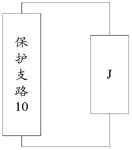
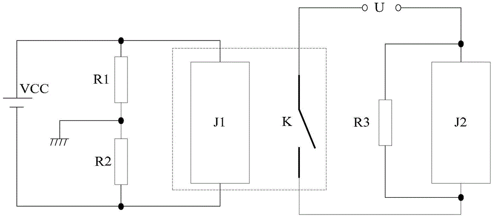
The invention discloses a controller protection circuit, which comprises a protection branch. The protection branch is connected in parallel at two ends of a control coil for releasing reverse voltage generated by the control coil. The control coil is the coil for controlling on and off of an inductive load power supply loop. The technical problem that the controller in the prior art is likely to interfere is solved, and effects of improving work stability of the controller are achieved.

Description

technical field [0001] The invention relates to the field of electronic circuits, in particular to a protection circuit for a controller. Background technique [0002] Various types of controllers used in oilfield automation systems such as Remote Terminal Unit (RTU for short), Programmable Logic Controller (PLC for short), when the controller is connected to industrial electrical equipment such as motors, transformers, relays, solenoid valves, etc. , These devices are inductive loads, which will generate high back electromotive force when switching, which may not only damage the components, but also generate high-frequency electromagnetic waves to interfere with other circuits, and directly invade the controller device through the power supply. Because the current change in the inductance coil will inevitably generate induced electromotive force, the higher the rate of current change, the greater the induced electromotive force. The low-frequency component of this induced ...

Claims


Application Information

Patent Timeline
IPC IPC(8): H02H9/04
Inventor 门虎丁慎花辛力陈宇吴斌沈勇
Owner PETROCHINA CO LTD
Learn More