Data flow transmission method and user equipment

A technology of data stream transmission and user equipment, applied in the field of communication, can solve problems such as inability to guarantee service quality and inflexible offloading, and achieve the effect of improving service quality assurance and flexible offloading

Inactive Publication Date: 2016-05-18
SHANGHAI HUAWEI TECH CO LTD
View PDF0 Cites 8 Cited by
  • Summary
  • Abstract
  • Description
  • Claims
  • Application Information

AI Technical Summary

Problems solved by technology

[0006] In the above method, for a certain data flow, it is either transmitted in the LTE network or in the WLAN network, and the offloading is not flexible enough; in addition, since a certain data flow can only be transmitted in a certain network, if the data flow If packet loss occurs in the flow, there will be no recovery mechanism, so the quality of service cannot be guaranteed

Method used


Image

  • Data flow transmission method and user equipment
  • Data flow transmission method and user equipment
  • Data flow transmission method and user equipment

Examples


Embodiment 1

[0080] Embodiment 1, UE authentication method 1 in WLAN:

[0081] In the embodiment of the present invention, the authentication of the UE in the WLAN mainly has the following two purposes:

[0082] 1. Identify user identity and prevent illegal user access;

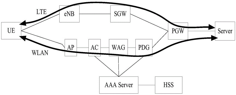
[0083] 2. After the identity of the user is identified, the link of the same user in the WLAN can be associated with the link in the LTE.

[0084] Wherein, the authentication method of the UE in the WLAN given in Embodiment 1 is described as follows:

[0085] 1) If the network side (such as eNB) thinks that authentication is required, it can initiate an authentication command (AuthenticationCommand) to the UE to trigger the authentication process of the UE;

[0086] 2) The UE initiates an authentication request (AuthenticationRequest) to the network side (such as eNB) in the WLAN, wherein the authentication request carries the C-RNTI and CellID of the UE to identify its own identity;

[0087]3) After receiving the abov...

Embodiment 2

[0094] Embodiment 2, UE authentication method 2 in WLAN:

[0095] In the second embodiment, the authentication method of the UE in the WLAN may adopt the existing 802.1x authentication method in the WLAN, wherein the authentication method is based on EAP-AKA. The second embodiment will not be described in detail here.

[0096] Since the authentication method of the UE in the LTE network is similar to the authentication method of the UE in the WLAN in Embodiment 2 and is independent of each other, after the WLAN link and the LTE link are established between the UE and the network side, You can associate WLAN links with LTE links in the following ways:

[0097] 1) Determine a unified user ID, which can be used to identify a user in both WLAN and LTE, such as the user's IMSI.

[0098] 2), the authentication process of UE in WLAN is a process independent of LTE authentication, but after the authentication is passed and the WLAN link is established, the user ID needs to be stored...

Embodiment 3

[0104] Embodiment 3, UE authentication method 3 in WLAN:

[0105] In the third embodiment, under the condition that the WLAN module and the LTE module of the UE are inseparable, the authentication process of the LTE is used to realize the authentication of the UE in the WLAN. The specific method is as follows:

[0106] 1), UE reports whether it supports WLAN in LTE, and WLANMACAddress; wherein, these WLAN information can be sent to the network side (such as eNB) through RadioCapabilitiesprocedure, or sent to the network side (such as eNB) through any other feasible LTEProcedure;

[0107] 2) When the UE establishes an LTE link, the network side (such as eNB) can obtain the WLAN capability and WLANMACAddress supported by the UE through LTE, and then scan the existing WLAN link according to the WLANMACAddress. If found, the WLAN link and LTE Links are associated so that the scheduling policy negotiation and data flow distribution process can be started later;

[0108] 3) When t...


PUM


Abstract

An embodiment of the invention relates to the field of communication technology, and discloses a data flow transmission method and user equipment, wherein the data flow transmission method comprises the steps of establishing a first network link and a second network link between the user equipment and a network side by the user equipment, wherein the first network is different from the second network; correlating the first network link with the second network link by the user equipment; and shunting a data flow to the first network link and the second network link for transmission by the user equipment according to a scheduling algorithm. The data flow transmission method and the user equipment can realize hybrid transmission of the same data flow in different networks. Compared with an existing data flow transmission method and existing user equipment, the data flow transmission method and the user equipment are advantageous in that more flexible shunting can be realized, and furthermore service quality can be improved.

Description

technical field [0001] The present invention relates to the technical field of communications, and in particular to a data stream transmission method and user equipment. Background technique [0002] In order to improve the throughput of the air interface, the current 3rd Generation Partnership Project (The3rdGenerationPartnershipProject, 3GPP) technology proposes a method of using Wireless Local Area Networks (WirelessLocalAreaNetworks, WLAN) and Long Term Evolution (LongTermEvolution, LTE) networks for mixed transmission of data streams. . Among them, the implementation of this method can refer to figure 1 In the system shown, the specific process is as follows: [0003] First, construct LTE network and WLAN network respectively. Among them, it mainly includes base station (eNB), serving gateway (ServingGateway, SGW), access point (AccessPoint, AP), access controller (AccessController, AC), WLAN access gateway (WLANAccessGateway, WAG), packet data gateway (PacketDataGa...

Claims


Application Information

Patent Timeline
Patent Type & Authority Applications(China)
IPC IPC(8): H04W28/02H04W28/06H04W28/10H04W76/02H04L45/24H04L45/243
CPCH04W28/0242H04W28/065H04W28/10H04L47/125H04L47/196H04B7/022H04L45/24H04W88/06H04W80/02H04L45/245H04L1/1854H04L1/1874H04W76/16H04W80/00H04W28/02H04W40/02
Inventor 李江黄敏马霓李永茂夏斌卢建民张毅
Owner SHANGHAI HUAWEI TECH CO LTD
Why Eureka
Try Eureka