
Micro-motion locking screw

A technology for locking screws and screws, which is applied in the direction of fixers, internal bone synthesis, fastening devices, etc. It can solve problems such as poor connection reliability, inability to pressurize the fracture site, and difficulty in connecting and assembling the tapered screw shaft and the threaded sleeve.

Inactive Publication Date: 2016-05-25
CHUANGHUI MEDICAL EQUIP JIANGSU
View PDF10 Cites 4 Cited by
  • Summary
  • Abstract
  • Description
  • Claims
  • Application Information

AI Technical Summary

Problems solved by technology

However, due to the deformation of the tapered screw shaft, the fracture site cannot be compressed during clinical use
In addition, the connection and assembly of the tapered screw shaft and the threaded sleeve is difficult, the connection reliability is poor, and the tapered screw shaft is prone to breakage in clinical use

Method used


Image

  • Micro-motion locking screw
  • Micro-motion locking screw
  • Micro-motion locking screw

Examples


Embodiment 1

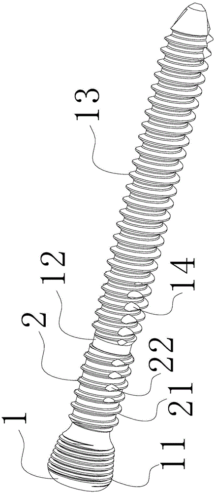
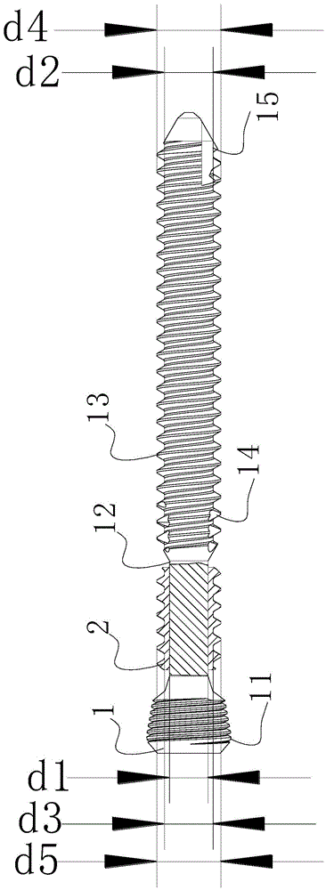
[0030] See figure 1 , figure 2 , Figure 4 , Figure 5 , Figure 6 , a micro-motion locking screw with a diameter of 5.5*50, the screw body 1 is made of stainless steel, the screw sleeve 2 is made of polylactic acid material, and the screw sleeve 2 is directly formed and fixed on the screw body 1 by injection molding. The screw body is composed of a locking thread 11, a connecting rod 12, a screw back self-tapping groove 14, a bone thread 13, and a screw-in self-tapping groove 15 which are sequentially connected. The bone thread 13 is a cortical bone thread. The diameter d1 of the connecting rod 12 on the screw body is equal to the minor thread diameter d2 of the bone thread 13 which is 4.0, the major thread diameter d4 of the bone thread 13 is 5.0, and the pitch is 1.3. The minor thread diameter d3 of the screw sleeve 2 is 4.5, the major thread diameter d5 is equal to the major thread diameter d4 of the bone thread 13 , and the outer surface of the screw sleeve 2 is pro...

Embodiment 2

[0032] See image 3 , a micro-motion locking screw with a diameter of 5.5*50, the screw body 1 is made of titanium alloy material, the screw sleeve 2 is made of polylactic acid material, and the screw sleeve 2 is directly formed and fixed on the screw body 1 by injection molding. The screw body is composed of a locking thread 11, a connecting rod 12, a screw back self-tapping groove 14, a bone thread 13, and a screw-in self-tapping groove 15 which are sequentially connected. The bone thread 13 is a cortical bone thread. The diameter d1 of the connecting rod 12 on the screw body is 3.5, the major thread diameter d4 of the bone thread 13 is 5.0, the minor thread diameter d2 is 4.0, and the pitch is 1.3. The small thread diameter d3 of the screw sleeve 2 is equal to the small thread diameter d2 of the bone thread 13, the major thread diameter d5 is equal to the major thread diameter d4 of the bone thread 13, and the outer surface of the screw sleeve 2 has no self-tapping groove....


PUM


Abstract

The invention relates to a micro-motion locking screw which comprises a screw body made of a non-biodegradable material; the screw body is fixedly provided with a screw sleeve made of a degradable material; the screw body is composed of a locking thread, a connection rod, a screw bone thread, screw returning self tapping slots and screw feeding self-tapping slots which are sequentially connected; the screw sleeve is provided with the screw bone thread. According to the micro-motion locking screw, pressurizing operation can be conducted in surgery, the screw sleeve can be degraded within 1-15 months, a bone close to the side of a locking bone connection plate can conduct micro motion after the screw sleeve is degraded, and thus growth of the bone is promoted under stimulus of force.

Description

technical field [0001] The invention relates to the technical field of fracture treatment and recovery, in particular to a micro-movement locking screw. Background technique [0002] When the locking plate and locking screw are used for fracture fixation, the locking plate, locking screw, and fracture are firmly fixed. And Wolf's law shows that the stimulation of force is beneficial to the growth of bone. Therefore, due to the slight bending of the screw on the side away from the locking plate, the bone can be stimulated by force, which is beneficial to the recovery of the fracture. On the side close to the locking bone plate, due to the stronger rigidity of the internal fixation, the bone is less likely to be stimulated by force, which is not conducive to the recovery of the fracture. The Chinese patent of CN202458652U discloses a dynamic locking screw, comprising a tapered screw shaft and a threaded sleeve that can be inserted into the tapered screw shaft. After using t...

Claims


Application Information

Patent Timeline
Patent Type & Authority Applications(China)
IPC IPC(8): A61B17/86
CPCA61B17/86A61B17/863A61B17/866A61B17/8685A61B2017/8655
Inventor 徐文利蔡勇
Owner CHUANGHUI MEDICAL EQUIP JIANGSU
Learn More