
Collection and purification system for thermal processing and oil fume processing

A technology of oil fume purification and purification system, which is applied in the direction of smoke removal, chemical instruments and methods, cleaning methods and utensils, etc., which can solve the problems of easy inhalation of flames, large air volume, wind speed and negative pressure, oil fume overflow, etc., to ensure oil fume Collection effect, effect of securing the ventilation rate

Inactive Publication Date: 2016-05-25
东风汽车悬架弹簧有限公司
View PDF0 Cites 4 Cited by
  • Summary
  • Abstract
  • Description
  • Claims
  • Application Information

AI Technical Summary

Problems solved by technology

[0003] Scattered multi-point collection: each collection cover is an open collection method, which requires a very large air volume, wind speed and negative pressure, and the oil fume generated has a high temperature and a fast rising speed, which is not easy to be caught, and the collection effect is often only 20-30%; At the same time, the flame generated by the workpiece entering the oil is easily sucked into the ventilation duct, igniting the oil and carbon deposits in the ventilation duct, causing a fire
[0004] Integral wind cover: Since the front side of the oil tank is the operation surface, and the rear side is the hydraulic system of the quenching machine and the quenching machine (the working state is swinging), it is impossible to adjust the oil tank by about 100M 2 The two sides are closed, the oil fume overflows, and the collection effect is often only 60-70%

Method used


Image

  • Collection and purification system for thermal processing and oil fume processing

Examples


Embodiment Construction

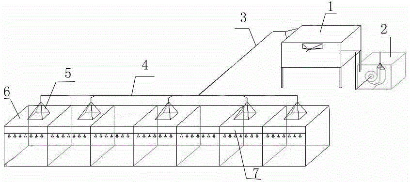
[0018] The present invention as figure 1 As shown, the oil fume collection and purification system of the heat treatment quenching line is taken as an example.

[0019] Heat treatment oil fume treatment and collection evolution system, including oil fume purification device 1, oil fume purification device 1 with suction fan 2, oil fume purification device 1 connected with main air duct 3, main air duct 3 is connected with sub-air duct 4, sub-air duct 4 A plurality of exhaust top covers 5 are connected with an integral wind cover 6, the two ends of the integral wind cover 6 are closed, and the front and rear sides are provided with air curtains 7 to lock the wind vertically.

[0020] A plurality of exhaust top covers 5 are cone-shaped, and the negative pressure zone of the air suction port of the exhaust top covers 5 is 2-2.5 meters away from the liquid surface of the oil tank.


PUM


Abstract

The invention provides a collection and purification system for thermal processing and oil fume processing. An oil fume purification device is equipped with a suction fan and connected to a main air duct; and the main air duct is connected to branch air ducts. The system is characterized in that the branch air ducts are connected to an overall fan housing by a plurality of ventilation top housings; two ends of the overall fan housing are sealed; air curtains are disposed on the front side and the rear side of the overall fan housing to implement vertical wind locking; and each ventilation top housing is designed into a conical type, and a negative-pressure area of an exhaust opening of the ventilation top housing is 2-2.5 m away from the liquid level of an oil tank. The system provided by the invention is characterized in that the overall fan housing carries out concentrative collection and is relatively sealed; two ends of the overall fan housing are sealed during oil fume collection; the two rows of air curtains are disposed on the two sides to implement the vertical wind locking and lock oil fume, so that the oil fume is prevented from leaking to front and rear sides, air outside the fan housing is prevented from entering, and a ventilation rate and an oil fume collection effect are guaranteed; and the multi-point uniform collection is realized at each dust generation point, the two ends are sealed physically, and the air curtains on the front and rear sides are used for the wind locking, so that the oil fume collection effect is ensured, and an oil fume collection rate reaches over 95%.

Description

technical field [0001] The invention relates to oil fume collection used in production workshops, in particular to a heat treatment oil fume treatment collection and purification system. Background technique [0002] At present, the heat treatment production workshop generally adopts two methods for the collection of multi-point scattered, flammable and explosive industrial waste gas: scattered multi-point collection and integral wind cover. [0003] Scattered multi-point collection: each collection cover is an open collection method, which requires a very large air volume, wind speed and negative pressure, and the oil fume generated has a high temperature and a fast rising speed, which is not easy to be caught, and the collection effect is often only 20-30%; At the same time, the flame generated by the workpiece entering the oil is easily sucked into the ventilation duct, igniting the oil and carbon deposits in the ventilation duct, causing a fire. [0004] Integral wind c...

Claims


Application Information

Patent Timeline
Patent Type & Authority Applications(China)
IPC IPC(8): B08B15/00
Inventor 王爱民王延平管斌华
Owner 东风汽车悬架弹簧有限公司
Learn More