Automatic shaft ribbing tool

A rib-pressing and automatic technology, applied in forming tools, manufacturing tools, metal processing equipment, etc., can solve the problems of affecting the machining accuracy of the shaft, low production efficiency, and the workpiece cannot be placed in place, so as to avoid the influence of artificial factors and improve the The effect of improving production efficiency and improving machining accuracy

Active Publication Date: 2016-05-25
NINGBO VISTART INTELLIGENT TECH
View PDF8 Cites 15 Cited by
  • Summary
  • Abstract
  • Description
  • Claims
  • Application Information

AI Technical Summary

Problems solved by technology

[0003] Existing presses used for ribbing of shaft workpieces are mainly realized by upper dies and lower dies. The lower mold corresponding to the mold is set on the upper end of the lower mold base of the press, and the lower mold base is set on the working table of the press. The beading process is mainly realized through the corresponding cutting edges on the upper mold and the lower mold. Inside the cutting edge of the lower die, the upper die seat drives the upper die to press down, so that the workpiece is beaded between the upper die and the lower die. This beading process realized on the press machine generally adopts manual loading and unloading during loading. , this not only increases the labor intensity of the operator, but the production efficiency is low, and sometimes the workpiece cannot be placed in the position, resulting in a poor chopping distance; When it is necessary to press eight ribs on the surface of the shaft, it is necessary to manually rotate the shaft 45 degrees for the second pressing after the first pressing. Such a rotation angle is difficult to grasp and requires the operator to master it skillfully. However, even for skilled workers, there is a certain error between each rotation, which affects the machining accuracy of the shaft

Method used


Image

  • Automatic shaft ribbing tool
  • Automatic shaft ribbing tool
  • Automatic shaft ribbing tool

Examples


Embodiment Construction

[0039] The present invention will be further described in detail below in conjunction with the accompanying drawings and embodiments.

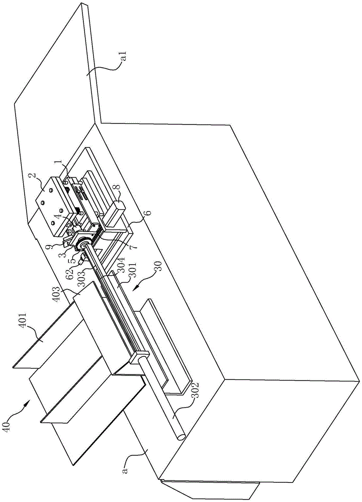
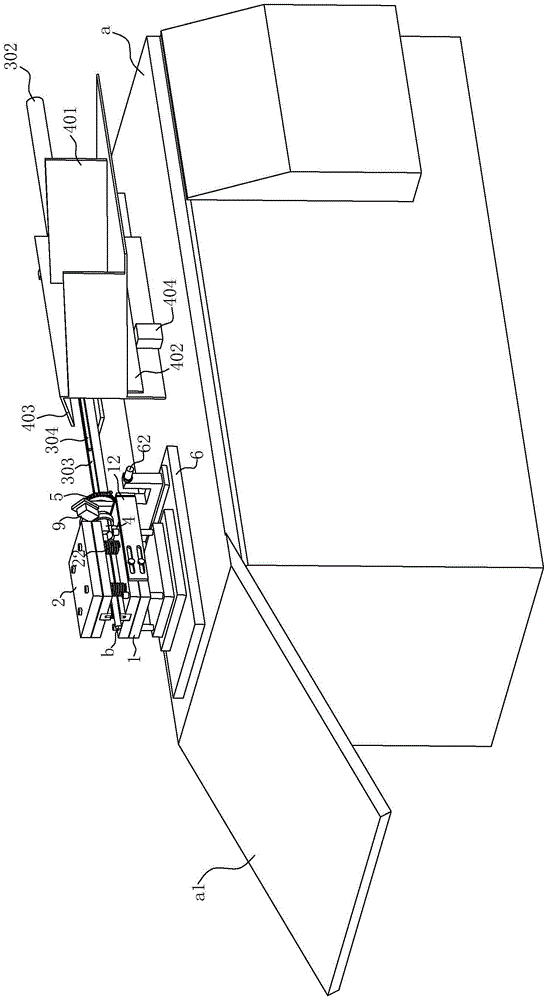
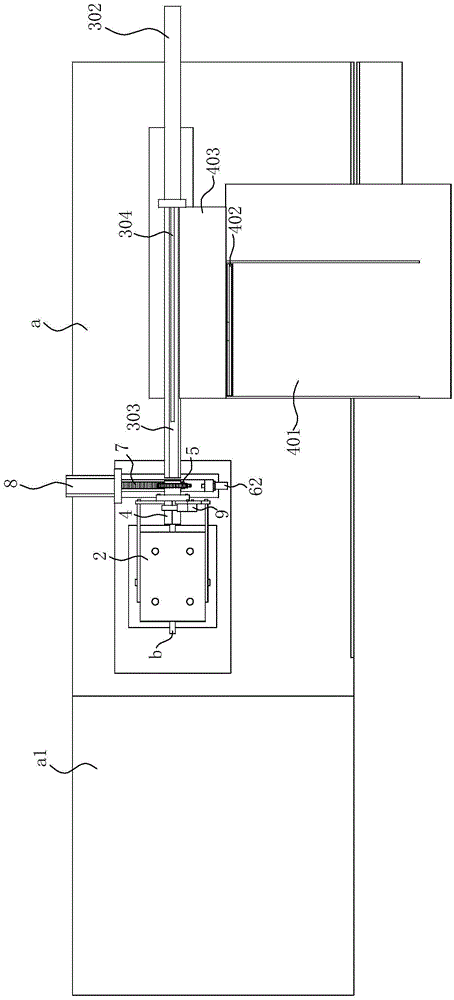
[0040] like Figure 1~5 As shown, the shaft automatic beading tooling of this embodiment includes a processing platform a, a lower mold base 1, an upper mold base 2, a lower beading mold 10, an upper beading mold 20, a driving mechanism 50, a mounting plate 3, and a clamp 4 , Gear 5, mounting seat 6, rack 7, first cylinder 8 and clamping cylinder 9.

[0041] Specifically, the lower mold base 1 is arranged on the processing platform a, the upper surface of the lower mold base 1 is provided with a first installation groove 11, and the lower beading mold 10 is arranged in the first installation groove 11 and has a first beading groove 100. The upper mold base 2 can move up and down and is located above the lower mold base 1, and a spring 22 is arranged between the upper mold base 2 and the lower mold base 1 to keep the upper mold base 2 moving ...


PUM


Abstract

The invention provides an automatic shaft ribbing tool. The automatic shaft ribbing tool comprises a machining platform, a lower die seat, an upper die seat, a lower ribbing die, an upper ribbing die, a driving mechanism, a mounting plate, a clamp, a gear, a mounting seat, a rack, a first air cylinder and a clamping air cylinder. The invention provides a mechanism capable of realizing automatic rotation of a shaft to be machined for a compression tool. When the automatic shaft ribbing tool is used, the upper die seat is pressed on the surface of the shaft to finish first time of ribbing; after the first time of ribbing is finished, the shaft to be machined is clamped by the clamping air cylinder, and the first air cylinder drives the rack to move from front to back, so that the gear is driven to rotate, and furthermore, the shaft to be machined in a clamp is driven to rotate; and after the shaft to be machined rotates for a pre-set angle, the driving mechanism drives the upper die seat to be pressed down so as to carry out second time of ribbing. With the adoption of the structure provided by the invention, the shaft to be machined does not need to be manually rotated, and can rotate for the pre-set angle completely through setting a distance, so that influences caused by artificial factors are avoided, and the machining precision of the shaft and the quality stability of a product are effectively improved; and meanwhile, compared with manual operation, the production efficiency is greatly improved.

Description

technical field [0001] The invention relates to the technical field of shaft processing equipment, in particular to an automatic beading tool for shafts. Background technique [0002] The shaft beading process is often processed by a press or a punching machine. Generally, manual operation is adopted, one person and one machine, the workpiece is placed in the beading mold, and the beading process is performed, and the material is manually operated up and down. For example, the Chinese invention patent application with the application publication number CN104128502A "A kind of armature shaft beading mold" (application number: CN201410349763.7), the Chinese utility model patent "shaft beading device" (application number: CN202137243U) with the authorized announcement number CN202137243U : CN201120200392.8) etc. all disclose the structure of beading device. [0003] Existing presses used for ribbing of shaft workpieces are mainly realized by upper dies and lower dies. The low...

Claims


Application Information

Patent Timeline
Patent Type & Authority Applications(China)
IPC IPC(8): B21D37/10B21D13/02
CPCB21D13/02B21D37/10
Inventor 贝国生
Owner NINGBO VISTART INTELLIGENT TECH
Why Eureka
Try Eureka