Eureka AIR delivers breakthrough ideas for toughest innovation challenges, trusted by R&D personnel around the world.

Clamping device capable of being used for conveniently clamping tire mold slide block

A tire mold and clamping device technology, used in positioning devices, clamping, manufacturing tools, etc., can solve the problems of single clamping device size, large space for clamps, and large number of clamping devices, etc. Improve production efficiency and secure clamping

Inactive Publication Date: 2016-05-25
QINGDAO AGRI UNIV
View PDF5 Cites 3 Cited by
  • Summary
  • Abstract
  • Description
  • Claims
  • Application Information

AI Technical Summary

Problems solved by technology

[0006] (1) The top surface of the clamping device is a curved surface, which is cumbersome to process, takes a long time to process and requires high precision;
[0007] (2) The size of the clamping device is single after processing, which can only meet the clamping of the same type of tire mold sliders, and the size of the clamping devices required by different tire mold sliders is different, resulting in a very large number of clamping devices. At the same time, due to the large amount of inventory, storing these fixtures also takes up a lot of space;
[0008] (3) Each fixture can only clamp and produce one kind of tire mold slider, and the utilization rate is low;
[0009] (4) Due to the rapid replacement of tire molds, about 50%-80% of the clamping devices need to be updated every 3-4 years, and a large number of special clamps are eliminated in the product replacement, resulting in great waste

Method used


Image

  • Clamping device capable of being used for conveniently clamping tire mold slide block
  • Clamping device capable of being used for conveniently clamping tire mold slide block
  • Clamping device capable of being used for conveniently clamping tire mold slide block

Examples


Embodiment Construction

[0033] In the following, the present invention will be specifically described through exemplary embodiments. It should be understood, however, that elements, structures and characteristics of one embodiment may be beneficially incorporated in other embodiments without further recitation.

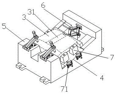
[0034] In the description of the present invention, it should be noted that the orientations or positional relationships indicated by "upper", "lower", "top", "bottom" etc. are based on the attached Figure 4 The positional relationship shown, and the description of direction words such as "front side", "rear side", "left side" and "right side", is based on the processing direction of the slideway on the tire mold slider, that is exist Figure 4 , the processing direction is Figure 4 The left and right horizontal directions in , where Figure 4 The left side is the front side described in the present invention. Similarly, other directions are based on the front side. What needs to be sai...


PUM


Abstract

The invention provides a clamping device capable of being used for conveniently clamping a tire mold slide block. The clamping device comprises a support block capable of being used for carrying the tire mold slide block, wherein the top surface of the support block is an inclined surface; when the tire mold slide block is put on the inclined surface of the support block, the top surface of the tire mold slide block is a horizontal surface; the front side of the support block is provided with a positioning block; the tire mold slide block is abutted against the positioning block; the back side of the support block is provided with a tail clamping unit; the tire mold slide block can be clamped in the forward and backward direction when the tail clamping unit is moved; stop blocks capable of doing reciprocating moving in the left and right directions are arranged at the left and right opposite sides of the support block; the stop blocks arranged on the two opposite sides are connected through a lead screw; when the lead screw rotates, the stop blocks simultaneously approach to the center of the tire mold slide block in the left and right directions or simultaneously and outwards move, so that the slide block center is kept unchanged; the automatic centering is realized. The clamping device can realize the multi-directional positioning, and can be changed according to the tire mold slide blocks in different dimensions, and the universality is realized.

Description

technical field [0001] The invention belongs to the field of tire building machinery, and in particular relates to a clamping device used for processing slideways on tire mold sliders. Background technique [0002] Tires are manufactured by injection molding in tire molds, and multiple tire mold sliders form a full circle, which is a unit group in tire processing. The tire mold slider moves from bottom to top along the upper slideway of the tire mold slider to form a complete closed tire mold to realize processing. After the processing is completed, the tire mold slider moves down along the slideway, and the tire mold is separated. , the injection molded tire is released from the mold. The tire mold slider obtains the ring-shaped whole of the slideway by integral injection molding, and divides it into equal parts (generally 9 equal parts) after cutting. [0003] see figure 1 , is the structural diagram of the tire mold slider, such as figure 1 As shown, the arc diameters...

Claims


Application Information

Patent Timeline
IPC IPC(8): B23Q3/08
CPCB23Q3/08B23Q3/065
Inventor 王方艳周建强
Owner QINGDAO AGRI UNIV
Why Eureka
Eureka Blog
Learn More