Shaft part polishing mechanism with high flexibility and use method thereof

A shaft part and polishing mechanism technology, applied in the polishing field, can solve the problems of complex workstation transfer steps, complex control procedures, etc., and achieve the effects of convenient use, simple device structure and reliable operation

Inactive Publication Date: 2016-05-25
叶绍月
View PDF6 Cites 2 Cited by
  • Summary
  • Abstract
  • Description
  • Claims
  • Application Information

AI Technical Summary

Problems solved by technology

Especially in the case of manual polishing, this polishing process that varies with different workpieces often involves more complicated and numerous polishing eq

Method used


Image

  • Shaft part polishing mechanism with high flexibility and use method thereof
  • Shaft part polishing mechanism with high flexibility and use method thereof
  • Shaft part polishing mechanism with high flexibility and use method thereof

Examples


Example Embodiment

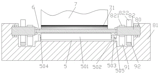
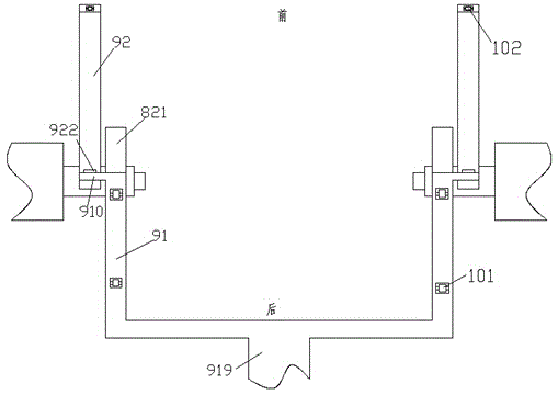
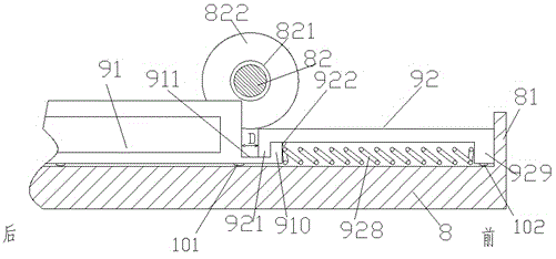
[0010] Combine below Figure 1-3 The present invention will be described in detail.

[0011] A polishing mechanism for shaft parts 6 with high flexibility according to an embodiment includes a polishing component 7 having a polishing strip 71 and a supporting base 8, both ends of which are rotatably supported by bearings 80, respectively There are clamping drive components 82 arranged symmetrically, two of the clamping drive components 82 are arranged opposite to each other so as to clamp the two ends of the shaft part 6 in place. The circumferential surface of each of the clamping drive components 82 A large gear 822 on the outer side and a small gear 821 on the inner side are fixedly installed on the upper part to mesh with the outer rack 92 and the inner rack 91 which are arranged symmetrically to drive the shaft part 6 against the polishing The strip 71 rotates relative to the polishing strip 71 for polishing operation. The rear end of each of the two inner racks 91 is fixed...


PUM


Abstract

The invention provides a shaft part polishing mechanism with high flexibility and a use method thereof. The device comprises a polishing part (7) with a polishing strip (71), and a supporting base (8). The two ends of the bearing base (8) rotationally support clamping drive parts (82) in bilateral symmetry through bearings (80) respectively, the two clamping drive parts (82) are oppositely arranged, and therefore the two ends of a shaft part (6) are clamped in place. A large gear (822) located on the outer side and a small gear (821) located on the inner side are fixedly installed on the circumferential surface of each clamping drive part (82) and used for being engaged with an outer rack (92) and an inner rack (91) in bilateral symmetry respectively, and then the shaft part (6) is driven to abut against the polishing strip (71) and relatively rotate relative to the polishing strip (71) to be subjected to polishing operation.

Description

technical field [0001] The invention relates to the field of polishing, in particular to a highly flexible shaft part polishing mechanism and a method for using the same. Background technique [0002] Where the dimensional accuracy of shaft parts is required to be high, polishing and grinding are often required. In order to achieve the required size, size processing and surface finish processing can be performed at the same time as grinding and polishing. This often requires the use of different polishing forces and spin speeds. In order to perform different polishing strategies according to different workpieces, it is often necessary to perform different polishing processes according to different workpiece conditions. Especially in the case of manual polishing, this polishing process that varies with different workpieces often involves relatively complicated and numerous polishing equipment workstations. This creates a disadvantage in terms of production costs and involv...

Claims


Application Information

Patent Timeline
IPC IPC(8): B24B29/04B24B47/12
CPCB24B29/04B24B47/12
Inventor 叶绍月
Owner 叶绍月
Why Eureka
Try Eureka