
Polishing device of fixing clamp with rotating mechanism for machining bearing washer

A technology of rotating mechanism and fixing fixture, applied in grinding/polishing safety devices, manufacturing tools, metal processing equipment, etc., can solve the problems of inconvenient fixation, small size of bearing washers, and inability to limit the position, so as to achieve easy installation and disassembly, The effect of increasing the contact area and increasing the polishing speed

Inactive Publication Date: 2019-10-11
东莞市史雷帝三维数控科技有限公司
View PDF1 Cites 6 Cited by
  • Summary
  • Abstract
  • Description
  • Claims
  • Application Information

AI Technical Summary

Problems solved by technology

[0003] The existing bearing washer polishing equipment does not have the function of turning over by itself. After polishing one side of the bearing washer, the staff needs to manually turn it over and then fix it, so that the other side can be processed, which prolongs the production cycle of the bearing washer , and increase the labor intensity of workers, the volume of the bearing washer is small, and it is inconvenient to fix. In view of the above problems, we propose a polishing device with a fixed fixture with a rotating mechanism for bearing washer processing
[0004] A high-efficiency tablet polishing device disclosed in the Chinese Invention Patent Application Publication No. CN107088822U. Although the structure of this high-efficiency tablet polishing device is novel, it can realize multi-angle polishing of tablets, with high polishing efficiency and good quality. , but the device can only polish one object at a time, and secondly, when the device polishes the object, it cannot limit its position

Method used


Image

  • Polishing device of fixing clamp with rotating mechanism for machining bearing washer
  • Polishing device of fixing clamp with rotating mechanism for machining bearing washer
  • Polishing device of fixing clamp with rotating mechanism for machining bearing washer

Examples


Embodiment Construction

[0027] The following will clearly and completely describe the technical solutions in the embodiments of the present invention with reference to the accompanying drawings in the embodiments of the present invention. Obviously, the described embodiments are only some, not all, embodiments of the present invention.

[0028] In the description of the present invention, unless otherwise stated, the meaning of "plurality" is two or more; the terms "upper", "lower", "left", "right", "inner", "outer" , "front end", "rear end", "head", "tail", etc. indicate the orientation or positional relationship based on the orientation or positional relationship shown in the drawings, and are only for the convenience of describing the present invention and simplifying the description, rather than Indicates or implies that the device or element referred to must have a particular orientation, be constructed and operate in a particular orientation, and therefore should not be construed as limiting the...


PUM


Abstract

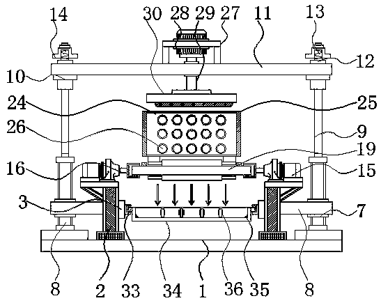
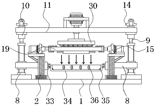
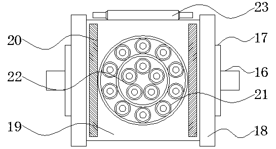
The invention discloses a polishing device of a fixing clamp with a rotating mechanism for machining a bearing washer, and relates to the technical field of bearing washer production. The polishing device comprises a supporting seat mechanism, a clamping mechanism and a waste material collecting box, wherein a supporting rod is welded above the supporting seat mechanism, a sliding rail is arrangedin a transverse plate, a first motor is fixedly arranged at the upper end of the supporting rod, the other end of a first transmission shaft is connected with an expansion plate, the clamping mechanism is positioned on the inner side of the expansion plate, and the left side surface and the right side surface of the waste collecting box are integrally connected with a sliding block. According tothe polishing device, through mutual cooperation among a sleeve, a limiting groove, a limiting column and a screw cap, an upper-layer plate can be combined and fixed at the upper end of a hydraulic rod, so that the overall structure of the device is high in flexibility and convenient to mount and dismount; the device is arranged with a storage plate through the clamping mechanism, the bearing washers can be overturned at the same time, and the device can be used for carrying out double-sided polishing on the bearing washers.

Description

technical field [0001] The invention relates to the technical field of bearing washer production, in particular to a polishing device with a fixed fixture of a rotating mechanism for processing a bearing washer. Background technique [0002] Bearing washers are annular parts of thrust rolling bearings with one or several raceways. The production of bearing washers requires a variety of processes, among which the polishing equipment for bearing washers belongs to one of them. Polishing refers to the use of mechanical, chemical or electrochemical effects. , to reduce the surface roughness of the workpiece to obtain a bright and flat surface, is to use polishing tools and abrasive particles or other polishing media to modify the surface of the workpiece. [0003] The existing bearing washer polishing equipment does not have the function of turning over by itself. After polishing one side of the bearing washer, the staff needs to manually turn it over and then fix it, so that th...

Claims


Application Information

Patent Timeline
Patent Type & Authority Applications(China)
IPC IPC(8): B24B27/00B24B55/06B24B41/02B24B41/06B24B7/16B24B55/00B24B41/00
CPCB24B7/16B24B27/0015B24B41/005B24B41/02B24B41/067B24B55/00B24B55/06
Inventor 黄红梅石宏孙锦民
Owner 东莞市史雷帝三维数控科技有限公司
Learn More