Eureka AIR delivers breakthrough ideas for toughest innovation challenges, trusted by R&D personnel around the world.

A fully automatic plastic injection mold for new energy auto parts

A technology for new energy vehicles and plastic injection molds, applied in the field of injection molds, can solve the problems of high surface temperature of products, a lot of manpower, hot hands, etc., to improve production efficiency, save manpower, and avoid contact burns.

Active Publication Date: 2017-12-12
JIANGSU XINLEI MOLD CO LTD
View PDF5 Cites 0 Cited by
  • Summary
  • Abstract
  • Description
  • Claims
  • Application Information

AI Technical Summary

Problems solved by technology

[0002] New energy vehicles are mainly composed of metal parts and plastic parts, and these plastic parts are mainly formed by injection molding. The injection mold of the prior art mainly includes an upper module and a lower module, an upper heating plate arranged above the upper module and The lower heating plate set under the lower module fills the injection cavity formed between the upper module and the lower module with plastic liquid to obtain the model of the plastic product. After the product is injected, it needs to be taken out in time, but due to the upper module and the lower module The injection molding cavity formed between the lower modules is a concave cavity, and the plastic product is not suitable to be taken out, and when the material is taken out manually, the temperature of the product surface is high, which is prone to scalding problems, and requires multiple people to operate the mold, requiring a lot of manpower

Method used


Image

  • A fully automatic plastic injection mold for new energy auto parts
  • A fully automatic plastic injection mold for new energy auto parts
  • A fully automatic plastic injection mold for new energy auto parts

Examples


Embodiment 1

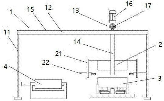
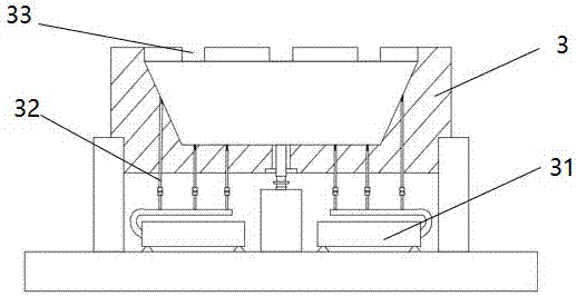
[0024] Embodiment 1: A fully automatic plastic injection mold for new energy automobile parts, including a frame, an upper module, a lower module and a conveying line, the frame includes a support column, a guide rail, a movable beam and a mechanical arm; the support column There are four; the guide rails are two, and are arranged in parallel on the top of the support column; the movable beam is arranged on the upper ends of the two guide rails, and can move along the guide rails; the mechanical arm is arranged on the movable beam; the upper module It is connected with the mechanical arm, and the upper module can move up and down along the mechanical arm; the lower module and the conveying line are arranged side by side under the frame; an injection cavity can be formed between the upper module and the lower module; the upper part of the upper module An upper heating plate is provided; a lower heating plate is provided below the lower module.

Embodiment 2

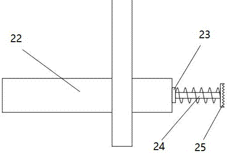
[0025] Embodiment 2: A fully automatic plastic injection mold for new energy automobile parts, including a frame, an upper module, a lower module and a conveying line, the frame includes a support column, a guide rail, a movable beam and a mechanical arm; the support column There are four; the guide rails are two, and are arranged in parallel on the top of the support column; the movable beam is arranged on the upper ends of the two guide rails, and can move along the guide rails; the mechanical arm is arranged on the movable beam; the upper module It is connected with the mechanical arm, and the upper module can move up and down along the mechanical arm; the lower module and the conveying line are arranged side by side under the frame; an injection cavity can be formed between the upper module and the lower module; the upper part of the upper module An upper heating plate is provided; a lower heating plate is provided under the lower module, and a toothed bar is provided on th...

Embodiment 3

[0026] Embodiment 3: A fully automatic injection mold for new energy automobile parts, including a frame, an upper module, a lower module and a conveying line, the frame includes a support column, a guide rail, a movable beam and a mechanical arm; the support column There are four; the guide rails are two, and are arranged in parallel on the top of the support column; the movable beam is arranged on the upper ends of the two guide rails, and can move along the guide rails; the mechanical arm is arranged on the movable beam; the upper module It is connected with the mechanical arm, and the upper module can move up and down along the mechanical arm; the lower module and the conveying line are arranged side by side under the frame; an injection cavity can be formed between the upper module and the lower module; the upper part of the upper module An upper heating plate is provided; a lower heating plate is provided below the lower module, and a second servo motor is provided on the...


PUM


Abstract

The invention discloses a full-automatic injection molding mold for new energy automobile parts. The injection molding mold comprises a rack, an upper mold block, a lower mold block and a conveying line; the rack comprises supporting columns, guide rails, a movable beam and a mechanism arm, the number of the supporting columns is four, the number of the guide rails is two and are arranged at the top ends of the supporting columns in parallel, the movable beam is arranged at the two ends of the two guide rails and can move along the guide rails, and the mechanism arm is arranged on the movable beam. The upper mold block is connected with the mechanical arm and can move up and down along the mechanical arm, the lower mold block and the conveying line are arranged below the rack side by side, and an injection molding cavity is formed between the upper mold block and the lower mold block. The requirement for full-automatic production of the interior parts of a new energy automobile can be met, automatic operation is completely adopted from plastic injection to demolding, manual work is not needed, labor is saved, accidents of touch scalds of staff are avoided, and the production efficiency can be improved greatly.

Description

technical field [0001] The invention relates to an injection mold, in particular to a fully automatic injection mold for producing parts of new energy vehicles. Background technique [0002] New energy vehicles are mainly composed of metal parts and plastic parts, and these plastic parts are mainly formed by injection molding. The injection mold of the prior art mainly includes an upper module and a lower module, an upper heating plate arranged above the upper module and The lower heating plate set under the lower module fills the injection cavity formed between the upper module and the lower module with plastic liquid to obtain the model of the plastic product. After the product is injected, it needs to be taken out in time, but due to the upper module and the lower module The injection molding cavity formed between the lower modules is a concave cavity, and the plastic product is not suitable to be taken out, and when the material is taken out manually, the temperature of ...

Claims


Application Information

Patent Timeline
Patent Type & Authority Patents(China)
IPC IPC(8): B29C45/43B29C45/42
CPCB29C45/4225B29C45/43
Inventor 郑兴慧沈维龙宦杰杨韩军周炳林曹炎培
Owner JIANGSU XINLEI MOLD CO LTD
Why Eureka
Eureka Blog
Learn More