
Clothes hanger supporting rod

A technology for a support rod and a clothes drying rod, which is applied to the field of clothes drying racks, can solve the problems of easy pulling out of the support rod from the soil, unreliable fixation of the support rod, and difficulty in installing the clothes drying rod, etc. Well-designed effects

Inactive Publication Date: 2016-05-25
夏其英
View PDF6 Cites 1 Cited by
  • Summary
  • Abstract
  • Description
  • Claims
  • Application Information

AI Technical Summary

Problems solved by technology

Especially rural households use more, and for solar radiation effect is good, usually clothes hanger is placed outdoors, and existing clothes hanger generally comprises a clothes hanger and the support bar that is arranged on clothes hanger two ends, but, existing The support bar structure of the current drying rack still has deficiencies: when encountering strong wind, the support bar is easy to pull out from the soil, the support bar is not fixed reliably, it is difficult to install the clothes hanger on the support bar, the clothes hanger is not easy to fix, and it is difficult to dry the clothes. The clothes rail is easy to fall under the wind, which is very inconvenient to use

Method used


Image

  • Clothes hanger supporting rod
  • Clothes hanger supporting rod

Examples


Embodiment Construction

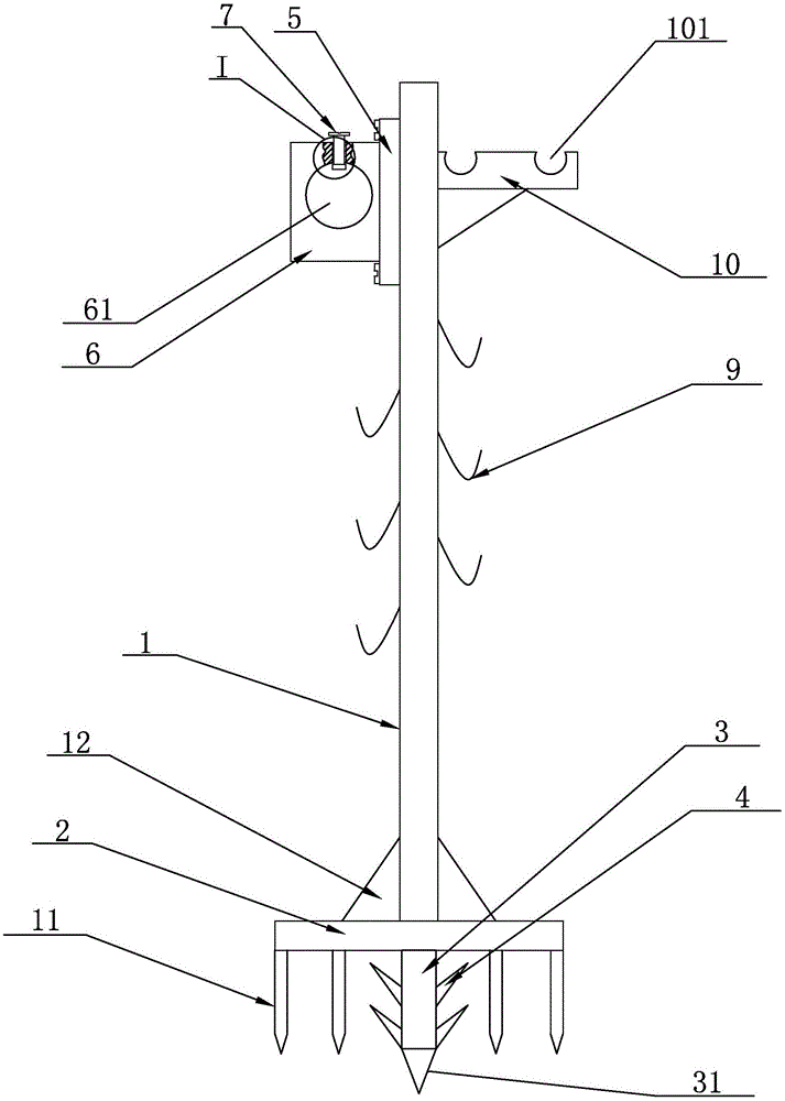
[0014] see figure 1 and figure 2 , a clothes hanger support rod disclosed by the present invention, comprising a support rod body 1, a positioning plate 2 is welded at the lower end of the support rod body 1, a positioning rod 3 is welded in the middle of the positioning plate 2, and the positioning rod 3 The longitudinal centerline of the support rod body 1 coincides with the longitudinal centerline of the support rod body 1, the lower end of the positioning rod 3 is provided with a sharp part 31, and a plurality of barbs 4 are welded on the positioning rod 3; the upper end of the support rod body 1 is detachable A clothes rail fixing device is provided, and the clothes rail fixing device includes a connecting seat 5 and a connecting plate 6 integrally provided with the connecting seat 5, the connecting seat 5 is connected to the side of the support rod body 1, and the connecting plate 6 A clothes-horse mounting hole 61 is arranged on the front end surface, and a connecting...


PUM


Abstract

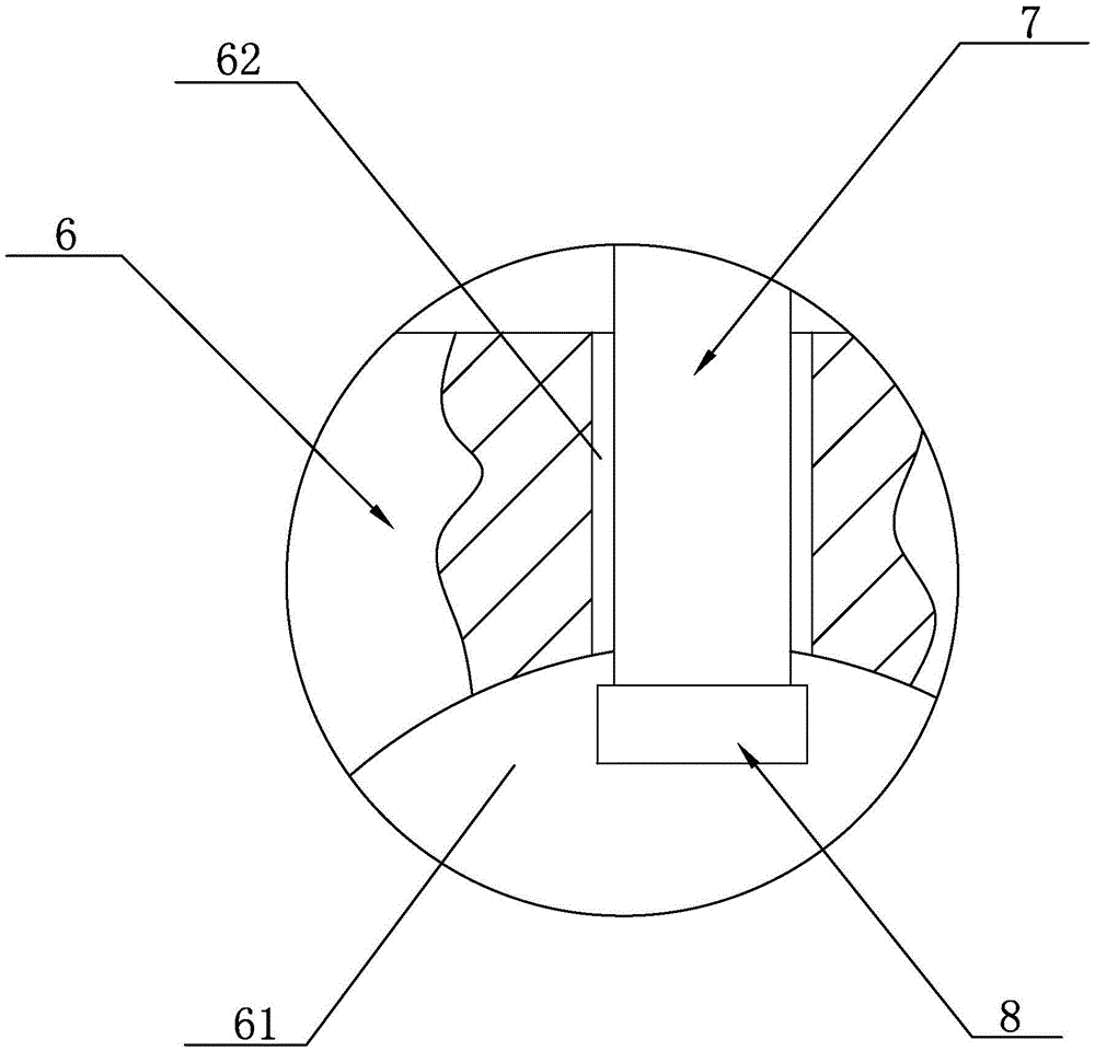
The invention discloses a clothes hanger supporting rod. The clothes hanger supporting rod comprises a supporting rod body, wherein a positioning plate is welded at the lower end of the supporting rod body; a positioning rod is welded in the middle of the positioning plate; a sharp spine part is arranged at the lower end of the positioning rod; a plurality of barbs are welded on the positioning rod; the upper end of the supporting rod body is detachably provided with a clothes hanging rod fixing device; the clothes hanging rod fixing device comprises a connection base and a connection plate which is integrated with the connection base; the connection base is connected with the side surface of the supporting rod body; a clothes hanging rod mounting hole is formed in the front end face of the connection plate; a connection screw hole is formed in the upper end face of the connection plate; the connection screw hole is internally connected with a locking bolt through threads; an anti-sliding sleeve sleeves the inner end of the locking bolt; the anti-sliding sleeve stretches into the clothes hanging rod mounting hole; and a plurality of hooks with upward openings are uniformly welded on the supporting rod body from bottom to top. With the adoption of the technical scheme, the clothes hanger supporting rod is reasonable in structural design and simple in structure; and the supporting rod can be fixed reliably and a clothes hanging rod is convenient to mount and does not easily fall off, so that the clothes hanger supporting rod is convenient to use.

Description

technical field [0001] The invention relates to the technical field of clothes drying racks, in particular to a clothes drying rack support rod. Background technique [0002] Clothes rack is a necessity in people's life and is used to dry various clothes. Especially rural households use more, and for the solar radiation effect is good, clothes hanger is usually placed outdoors, and existing clothes hanger generally comprises a clothes hanger and the support bar that is arranged on clothes hanger two ends, but, existing The support rod structure of the current drying rack still has deficiencies: when encountering strong wind, the support rod is easy to pull out from the soil, the support rod is not fixed reliably, it is difficult to install the clothes drying rod on the support rod, the clothes drying rod is not easy to fix, and the The clothes rail is easy to fall under the blowing of the wind, which is very inconvenient to use. Contents of the invention [0003] Aiming ...

Claims


Application Information

Patent Timeline
Patent Type & Authority Applications(China)
IPC IPC(8): D06F57/00
CPCD06F57/00
Inventor 夏其英
Owner 夏其英
Learn More