Monitoring device preset position setting method, monitoring device preset position switching method, and corresponding systems
A monitoring device and preset technology, which are applied in closed-circuit television systems, image data processing, instruments, etc., can solve problems such as unsatisfactory monitoring effects and unreasonable preset settings.
- Summary
- Abstract
- Description
- Claims
- Application Information
AI Technical Summary
Problems solved by technology
Method used
Image
Examples
Embodiment 1
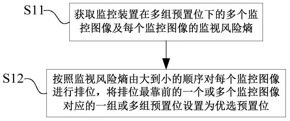
[0085] This embodiment provides a monitoring device preset position setting method, such as image 3 shown, including:
[0086] S11. Obtain multiple monitoring images of the monitoring device under multiple sets of preset positions and the monitoring risk entropy of each monitoring image, the monitoring risk entropy is used to represent the risk of the monitoring device to unsafe events or events of interest in the monitored scene or information availability.
[0087] S12. Rank each monitoring image in descending order of monitoring risk entropy, and set one or more sets of preset positions corresponding to one or more monitoring images at the top of the ranking as preferred preset positions .
[0088] Specifically, the monitoring device described in steps S11 and S12 can be a camera with a fixed viewing angle, or a camera with a controllable viewing angle. Only select the preset position of the monitoring image when the monitoring risk entropy is the largest as the preferr...
Embodiment 2
[0132] In embodiment 1, in order to be able to select a better preset position, it is necessary to adjust the viewing angle range of the monitoring device and traverse each preset position of the monitoring device. Therefore, the period of the previous test is relatively long. In order to further shorten the test period, in the implementation On the basis of Example 1, the method for setting the preset position of the monitoring device described in this embodiment further optimizes Embodiment 1, such as Figure 4 shown, including:
[0133] S21. Acquire a wide-angle surveillance image when the surveillance device is at a maximum viewing angle position.
[0134] S22. Divide the wide-angle monitoring image into multiple sub-monitoring images.
[0135]S23. Select one of the sub-monitoring images as a reference monitoring image and obtain its monitoring risk entropy, which is used to indicate the mastery degree of the monitoring device to the risks or information of unsafe events ...
Embodiment 3
[0142] This embodiment provides a method for switching between preset positions of a monitoring device acquired through the method for setting preset positions of a monitoring device described in Embodiment 1 and Embodiment 2, including:
[0143] According to the temporal and spatial correlation between the temporal and spatial statistical characteristics of the moving target and the monitoring images corresponding to the preferred preset positions, the switching time and order of the preferred preset positions are set.
[0144] Specifically, in the method for switching between preset positions described in this embodiment, the cruising path during preset position switching is not fixed, but is automatically adjusted in real time according to the changing characteristics of the moving target in time and space, which is convenient and flexible. , which can effectively monitor rapidly changing scenes and achieve the best monitoring and capture effect.
PUM
 Abstract
Description
Claims
Application Information
 - R&D
- Intellectual Property
- Life Sciences
- Materials
- Tech Scout
- Unparalleled Data Quality
- Higher Quality Content
- 60% Fewer Hallucinations
Browse by: Latest US Patents, China's latest patents, Technical Efficacy Thesaurus, Application Domain, Technology Topic, Popular Technical Reports.
© 2025 PatSnap. All rights reserved.Legal|Privacy policy|Modern Slavery Act Transparency Statement|Sitemap|About US| Contact US: help@patsnap.com


