Cutter wear estimating and monitoring method and system based on characteristic fusion

A feature fusion and tool wear technology, applied in the direction of manufacturing tools, metal processing machinery parts, maintenance and safety accessories, etc., can solve the problem of low tool state accuracy, insufficient application of multi-dimensional information and related information, and insufficient wear state sensitivity. And other issues

Active Publication Date: 2019-12-13
友机技术(上海)有限公司
View PDF13 Cites 33 Cited by
  • Summary
  • Abstract
  • Description
  • Claims
  • Application Information

AI Technical Summary

Problems solved by technology

However, the current methods generally have certain defects: (1) Most of them only collect a single signal, such as spindle current signal, vibration signal, temperature signal, acoustic emission, etc., and use a single signal to extract a single feature for tool wear status recognition. The limitations of signals or features are large; (2) Although a variety of signals are collected, the extracted signal features are not sensitive enough to the wear state of the tool, or a single analysis technique is used to extract signal features for different signals. The accuracy of identification and monitoring is not high; (3) A variety of features are extracted from the selected signal, but the analysis of features and wear status is mostly univariate and unidimensional trend analysis, which can reflect limited wear status, and the analysis of each feature Multi-dimensional information and relational information are not fully utilized
Use these features directly for tool wear assessment and monitoring. It is often difficult to reflect the real performance status and change rules of the tool and comprehensively evaluate the real health status of the tool under complex and changeable working conditions. The obtained evaluation results and monitoring There is also a big difference between the strategy and the actual situation

Method used


Image

  • Cutter wear estimating and monitoring method and system based on characteristic fusion
  • Cutter wear estimating and monitoring method and system based on characteristic fusion
  • Cutter wear estimating and monitoring method and system based on characteristic fusion

Examples


Embodiment Construction

[0056] Below in conjunction with accompanying drawing and specific embodiment the present invention is described in further detail:

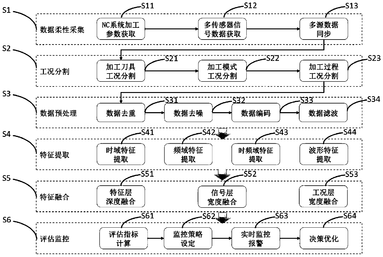
[0057] Such as figure 1 , a method for evaluating and monitoring tool wear based on feature fusion, which has the following features, including the following steps: Step (1), flexible data acquisition: based on the flexible data acquisition interface adopted by the system, the processing parameter data of the NC system is obtained and used for Reflect the sensor signal data of the tool state, and complete multi-source data synchronization to obtain a complete raw data set for tool monitoring and evaluation The data acquisition interface adopted is fully compatible with the company's current various NC systems and various tool monitoring sensor signals, from which the data required for analysis and optimization can be obtained as needed; step (2), working condition segmentation: for the obtained in step (1) Raw data, after the processing of eac...


PUM


Abstract

The invention relates to the technical field of machining, in particular to a cutter wear estimating and monitoring method and system based on characteristic fusion. The method comprises the steps ofdata flexible acquisition, working condition division, data preprocessing, characteristic extraction, characteristic fusion and estimation and monitoring. The system comprises a working condition division module, a data preprocessing module, a characteristic extraction module, a characteristic fusion module, an estimation and monitoring module and a self-learning module serially connected in sequence. The method and the system can realize multi-signal, multi-working-condition and multi-dimension fusion of original signals to obtain characteristic indexes capable of comprehensively reflecting the cutter wear state for estimating cutter real performance state and change rules to give more precise timely prewarning, alarm and feedback optimization policies. Through improvement of cutter wearonline estimation and monitoring performances, the machining problems caused by cutter wear are gradually solved, and the cost reduction, the quality improvement and the efficiency improvement in themachining process are finally achieved.

Description

technical field [0001] The invention relates to the technical field of mechanical processing, in particular to a method and system for evaluating and monitoring tool wear based on feature fusion. Background technique [0002] High-speed machining is an important part of advanced machining and manufacturing industries, and its advantages lie in extremely high machining accuracy, extremely fast machining efficiency and excellent machined surface quality. In the case of relatively stable processing equipment, processing technology and workpiece materials, the state of processing tools becomes a key factor in determining the cost, quality and efficiency of high-speed machining processes. However, as the machining process progresses, tool wear is inevitable. Unreasonable wear, tool use and tool change will first directly cause the loss of the tool and increase the cost; secondly, when machining at high speed, the temperature in the contact area with the workpiece will rise sharp...

Claims


Application Information

Patent Timeline
Patent Type & Authority Applications(China)
IPC IPC(8): B23Q17/09B23Q11/00
CPCB23Q11/0089B23Q17/0957
Inventor 吴亚君张开恒陈阳
Owner 友机技术(上海)有限公司
Why Eureka
Try Eureka