A household electric lifting device

A lifting device, electric technology, applied in electromechanical devices, electric components, door/window protection devices, etc., can solve the problems affecting the service life of the lifting device, short up and down strokes, unfavorable large-scale production, etc., to enhance self-locking. and stability, small commutation gap and compact structure

Active Publication Date: 2017-04-05
ZHEJIANG YONG HUI APPLIANCE CO LTD
View PDF8 Cites 0 Cited by
  • Summary
  • Abstract
  • Description
  • Claims
  • Application Information

AI Technical Summary

Problems solved by technology

The AC type electric lifting device is widely used because of its small size and the winding mechanism can adjust the up and down stroke. However, this device also has many disadvantages. First, the device vibrates greatly during operation and generates large noise, which affects the home. environment; secondly, the device will cause the motor to overheat during operation, and it is easy to cause the motor to stop running, thus affecting the service life of the lifting device; thirdly, the device has high manufacturing cost and high market price, which is not conducive to large-scale production
Although the DC electric lifting device has the advantages of low noise, stable operation, low price, and good self-locking effect, the device is bulky and the up and down stroke is short.

Method used


Image

  • A household electric lifting device
  • A household electric lifting device
  • A household electric lifting device

Examples


Embodiment Construction

[0022] In order to make the object, technical solution and advantages of the present invention clearer, the present invention will be further described in detail below in conjunction with the accompanying drawings and embodiments. It should be understood that the specific embodiments described here are only used to explain the present invention, not to limit the present invention.

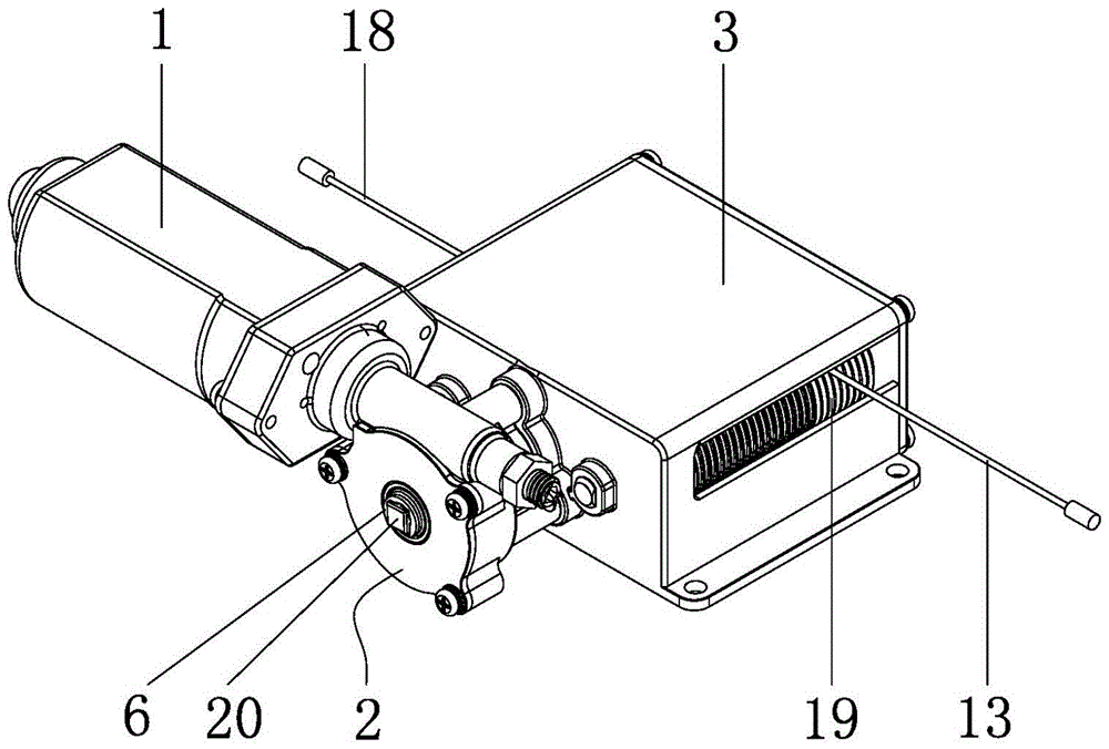
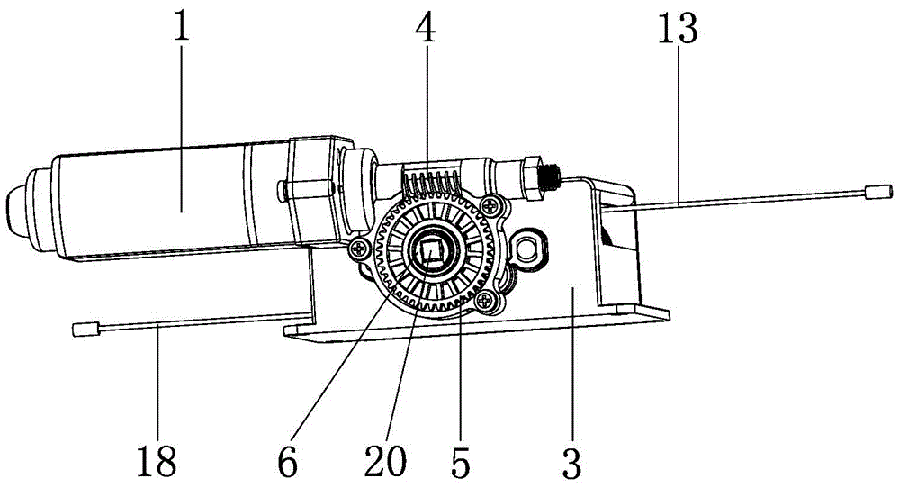
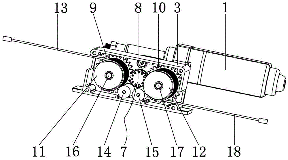
[0023] see Figure 1 to Figure 9 As shown, the home electric lifting device of the embodiment of the present invention includes a motor 1, a box body 3, a first-stage deceleration mechanism 2, and a second-stage deceleration mechanism 7. The first-stage deceleration mechanism 2 is connected to the driving end of the motor 1, and the box body 3 is connected to one side of the driving end of the motor 1 through the first-stage deceleration mechanism 2, and the second-stage deceleration mechanism 7 is arranged inside the box body 3.

[0024] see figure 1 , figure 2 , Figure 5 and Figure 7 As s...


PUM


Abstract

The invention discloses a domestic electric hoisting device. The domestic electric hoisting device comprises a motor, and a box body which is connected to a motor driving end through a first-grade speed reducing mechanism, wherein the first-grade speed reducing mechanism comprises a first-grade speed reducing worm rod connected with the motor driving end and a first-grade speed-reducing worm wheel engaged with the first-grade speed reducing worm rod; a driving shaft sleeves the first-grade speed-reducing worm wheel; one end of the driving shaft stretches into the box body and a second-grade speed reducing mechanism is arranged at the end part of the driving shaft; the second-grade speed reducing mechanism comprises a first speed reducing gear fixed at the end part of the driving shaft; a second speed reducing gear and a third speed reducing gear are engaged with the left and right sides of the first speed reducing gear, respectively; a first rope wheel and a second rope wheel are arranged on the second speed reducing gear and the third speed reducing gear, respectively; a first steel wire rope and a second steel wire rope winds the first rope wheel and the second rope wheel, respectively; and the end parts of the first steel wire rope and the second steel wire rope stretch out of the box body. With the adoption of the domestic electric hoisting device, speed reduction is realized twice; and the device has the advantages of small noises, small size, long hoisting route, stability in operation, long service life and good self-locking effect.

Description

technical field [0001] The invention belongs to the technical field of lifting devices, and in particular relates to a household electric lifting device applied to rolling shutter doors, drying racks and curtains. Background technique [0002] The lifting device is applied to rolling shutter doors, drying racks and curtains, mainly to control the free lifting of rolling shutter doors, drying racks and curtains. At present, conventional lifting devices mainly have two forms: manual and electric. Although the hand-operated lifting device is cheap, this traditional hand-operated lifting device has an ugly appearance and cannot meet the needs of modern people for high-quality life. The electric lifting device mainly realizes free lifting through the motor, but it is difficult to achieve the purpose of lifting only by the output torque of the motor, so a reduction mechanism is needed to achieve deceleration, so as to achieve the purpose of increasing the output torque. Existing...

Claims


Application Information

Patent Timeline
Patent Type & Authority Patents(China)
IPC IPC(8): E06B9/68H02K7/116
CPCE06B9/68H02K7/116
Inventor 于辉朱宏军吴和锋
Owner ZHEJIANG YONG HUI APPLIANCE CO LTD
Why Eureka
Try Eureka