
A flexible composite lining pipe connection device

A lining pipe, flexible technology, applied in the direction of hose connection devices, pipes/pipe joints/fittings, hoses, etc., can solve the problems of difficult to control the curing time of the adhesive, small application range, uneven thickness, etc., to achieve Significant economic benefits, reasonable and practical structural design, and high-quality lining

Active Publication Date: 2017-10-20
SHANDONG KELINRUIER PIPELINE ENG
View PDF6 Cites 0 Cited by
  • Summary
  • Abstract
  • Description
  • Claims
  • Application Information

AI Technical Summary

Problems solved by technology

Since this technology uses a binder as an intermediate medium, it is difficult to control the curing time of the binder. If the temperature is too low, it is necessary to take heating measures to consume a lot of heat energy.
In addition, because the adhesive will flow before it is cured, if the curing time cannot keep up, the lined pipe will sometimes appear in a state of uneven thickness, the quality of the lined is poor, and the connection between the cured composite lined and the pipe is also difficult. It is relatively simple, so the existing composite hose lining technology lining pipes cannot withstand high pressure, and can only be used in low-pressure pipes or sewage pipes, and there is a problem of small application range

Method used


Image

  • A flexible composite lining pipe connection device
  • A flexible composite lining pipe connection device

Examples


Embodiment Construction

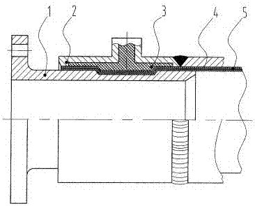
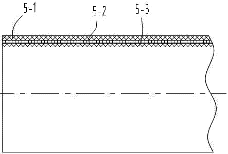
[0008] like figure 1 , figure 2 As shown, a flexible composite lining pipe connecting device is mainly composed of a connecting head 1, an outer sleeve 2, a cured product 3, a pipeline 4, a flexible composite lining pipe 5, a protective layer 5-1, and an aramid fiber reinforced layer 5. -2. The anti-seepage inner film layer is composed of 5-3; the protective layer 5-1, the aramid fiber reinforced layer 5-2, and the anti-seepage inner film layer 5-3 are stacked and solidified into a cylindrical structure. 5-1 is the outer layer, the anti-seepage inner film layer 5-3 is the inner layer, the aramid fiber reinforced fiber layer 5-2 is between the two, the flexible composite lining pipe 5 is lined in the pipe 4, and the aramid fiber reinforced fiber Layer 5-2 is initially a diamond-shaped mesh structure, which makes it easy to change the shape of the cylindrical flexible composite lining pipe, which is convenient for installation operations and does not damage its internal struct...


PUM


Abstract

Disclosed is a flexible composite lining pipe (5). The flexible composite lining pipe (5) comprises a protection layer (5-1), a reinforced fibre layer (5-2) and a seepage-proof inner film layer (5-3). The three layers are compositely telescoped and cured into a flexible composite lining pipe (5), and the flexible composite lining pipe (5) is lined in a pipeline (4). The reinforced fibre layer (5-2) is a diamond network structure, is lined in the front of the pipeline (4) in the flexible composite lining pipe (5), and connects an outer sleeve (2) of a connection device and the pipeline (4) as a whole. A portion of a connector (1) is inserted into the flexible composite lining pipe (5), and a portion of the connector (1) exposed on the flexible composite lining pipe (5) is a connection end. An outer wall of the connector (1) inserted into the flexible composite lining pipe (5) is provided with a groove which enables a front end of the connector to be a clamping platform. A groove is provided inside the outer sleeve (2), and an inner diameter of a groove portion is larger than an inner diameter of two ends. An injecting hole is provided on the outer sleeve (2), and the injecting hole corresponds to the groove thereon. A curing product (3) is injected via the injecting hole, which enables the flexible composite lining pipe (5) between the outer sleeve (2) and the connector (1) to deform so as to reduce the diameter in the section of the groove on the outer wall of the connector (1) and to be clamped by the clamping platform at the front end of the connector (1) so that the flexible composite lining pipe (5) and the lining of the pipeline (4) are integrated.

Description

technical field [0001] The invention relates to the technical field of lining pipe connection, in particular to a flexible composite lining pipe connecting device. Background technique [0002] At present, the widely used technology of lining the composite hose inside the pipeline is to make the composite soft liner in advance, add a binder (resin) inside the composite hose, and then pull it into the pipeline by turning or pulling, and then pulling it into the pipeline. Then use hot steam pressurization, hot water circulating heating, compressed air and ultraviolet light to cure the adhesive on the composite liner, so that the composite liner in the pipeline can be rounded or tightly attached to the inner wall of the pipeline to achieve Pipe lining. Since this technology has a binder as an intermediate medium, the curing time of the binder is difficult to grasp. If the temperature is too low, heating measures must be taken to consume a large amount of heat energy. In addit...

Claims


Application Information

Patent Timeline
Patent Type & Authority Patents(China)
IPC IPC(8): F16L11/00F16L33/22B32B1/08B32B27/02B32B27/34B32B27/06
CPCF16L11/00
Inventor 周天航商海光刘晓东王春锋刘茂政陈浩
Owner SHANDONG KELINRUIER PIPELINE ENG
Learn More