Method and apparatus for detecting relation between evanescent field and Goos-Hanchen displacement, and optical device

An evanescent field and relationship technology, applied in the field of optics, can solve problems such as the inability to control the Goose-Hanchen displacement and the limited application of the Goose-Hanchen displacement.

Active Publication Date: 2016-05-25
NANKAI UNIV
View PDF5 Cites 2 Cited by
  • Summary
  • Abstract
  • Description
  • Claims
  • Application Information

AI Technical Summary

Problems solved by technology

[0004] The embodiment of the present invention provides a method, device and optical device for detecting the relationship between the evanescent field and the Goos-Hanchen displacement, aiming to solve the problem that the existing tec

Method used


Image

  • Method and apparatus for detecting relation between evanescent field and Goos-Hanchen displacement, and optical device
  • Method and apparatus for detecting relation between evanescent field and Goos-Hanchen displacement, and optical device
  • Method and apparatus for detecting relation between evanescent field and Goos-Hanchen displacement, and optical device

Examples


Embodiment 1

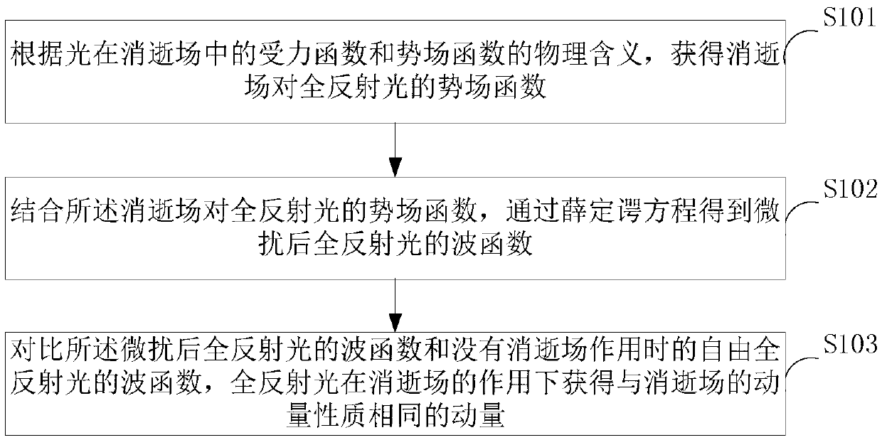
[0062] figure 1 The implementation flow of the method for detecting the relationship between the evanescent field and the Goose-Hanchen displacement provided by Embodiment 1 of the present invention is shown, and the details are as follows:

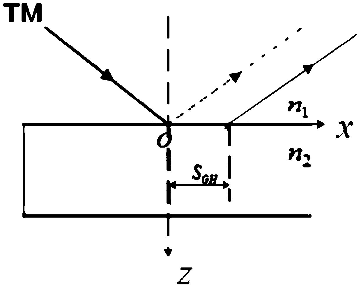
[0063] It should be noted, figure 2 It shows the schematic diagram of Gouss-Hanchen displacement. In the incident plane xoz, the TM plane light is incident from the optically denser medium to the optically rarer medium. When the incident angle is larger than the critical angle, total reflection occurs, and the totally reflected beam has relative to the incident point A displacement, that is, the Goos-Hanchen displacement, such as figure 2 As shown, when light is totally reflected on the medium interface, it can be known from the electromagnetic field boundary conditions that there is an electromagnetic field in the optically sparse medium, that is, the evanescent field. In 2012, FedorIFedorov pointed out in the article: the tangential...

Embodiment 2

[0091] Image 6 A specific structural block diagram of the device for detecting the relationship between the evanescent field and the Goose-Hanchen displacement provided by Embodiment 2 of the present invention is shown. For the convenience of description, only the parts related to the embodiment of the present invention are shown. In this embodiment, the device for detecting the relationship between the evanescent field and the Goos-Hanchen displacement includes: a potential field acquisition unit 61, a wave function acquisition unit 62, and a momentum acquisition unit 63, and the wave function acquisition unit 62 includes a relationship establishment module, A potential field acquisition module and a wave function acquisition module.

[0092] Wherein, the potential field acquisition unit 61 is used to obtain the potential field function of the evanescent field to the total reflection light according to the force function of light in the evanescent field and the physical mean...


PUM


Abstract

The invention is applied to the technical field of optics, and provides a method and apparatus for detecting a relation between an evanescent field and Goos-Hanchen displacement, and an optical device. The method comprises the following steps: according to physical meanings of a stress function and a potential field function of light in the evanescent field, obtaining a potential field function of the evanescent field for total-reflection light; through combination with the potential field function of the evanescent field for the total-reflection light, obtaining a wave function of the total-reflection light after perturbation through a Schrodinger equation; and comparing the wave function of the total-reflection light after the perturbation with a wave function of free total-reflection light without an evanescent field effect, and the total-reflection light obtaining momentum having the same momentum property as the evanescent field under the effect of the evanescent field. According to the invention, better regulation and control of the Goos-Hanchen displacement can be realized, and the Goos-Hanchen displacement can be better applied to such fields as optical sensors, all-optical switches, light beam displacement modulators and the like.

Description

technical field [0001] The invention belongs to the field of optical technology, and in particular relates to a method, a device and an optical device for detecting the relationship between an evanescent field and a Goos-Hanchen displacement. Background technique [0002] When the light is totally reflected on the surface of the medium, according to the analysis of the electromagnetic theory of light, it shows that there is also an electromagnetic field in the optically sparse medium, and the totally reflected light has a small displacement in the lateral direction relative to the incident point, because the displacement is determined by Goos and Hanchen found that it is called Goos-Hanchen displacement, also known as Goos-Hanchen displacement, referred to as G—H displacement. With the discovery of the Goos-Hanchen shift, the research on the mechanism of the Goos-Hanchen shift has become a hot spot. [0003] There are currently two views generally accepted: the first view i...

Claims


Application Information

Patent Timeline
IPC IPC(8): G01B11/02G02F1/01
CPCG01N21/552G01B11/02G02F1/01
Inventor 陈平李铭刘伟伟林列
Owner NANKAI UNIV
Why Eureka
Try Eureka