Onsite fire hose detection device quick in water filling and pressure stabilizing

A fire hose, on-site detection technology, applied in the direction of using stable tension/pressure to test the strength of materials, etc., can solve the problems of small flow, cannot be maintained, and cannot meet the detection standards, and achieve accurate detection results, easy transportation, Detect quick effects

Active Publication Date: 2016-05-25
应急管理部四川消防研究所
View PDF7 Cites 0 Cited by
  • Summary
  • Abstract
  • Description
  • Claims
  • Application Information

AI Technical Summary

Problems solved by technology

[0002] The existing fire hose on-site detection device has the following defects during use: 1) It cannot quickly fill the fire hose with water. According to the "Fire Hose" GB6246-2011 testing standard, it is required to fill the 1.2m fire hose within 1 minute. The water hose, and the previous detection device has only one water inlet, that is, the water outlet of the booster pump. The flow and velocity of the booster pump determine the water filling speed of the fire hose, so most of them fail to meet the detection standards In addition, the water inlet of the previous device was a tap water pipe, and the fire hydrant was not used to enter the water, so the flow rate was small, and most of them could not meet the requirements of fast water filling; 2) The existing device can only detect the 1.2m fire hose experiment Pressure, working pre

Method used


Image

  • Onsite fire hose detection device quick in water filling and pressure stabilizing
  • Onsite fire hose detection device quick in water filling and pressure stabilizing
  • Onsite fire hose detection device quick in water filling and pressure stabilizing

Examples


Embodiment

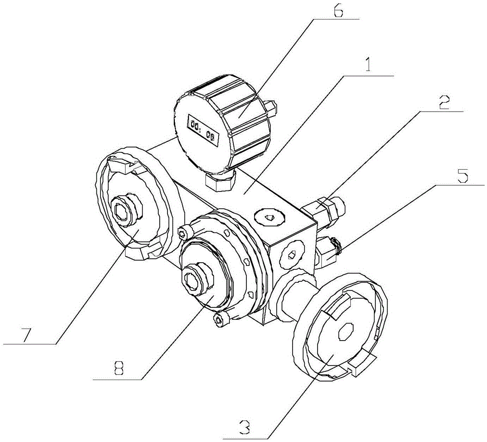
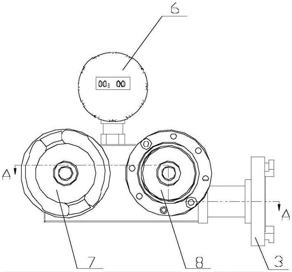
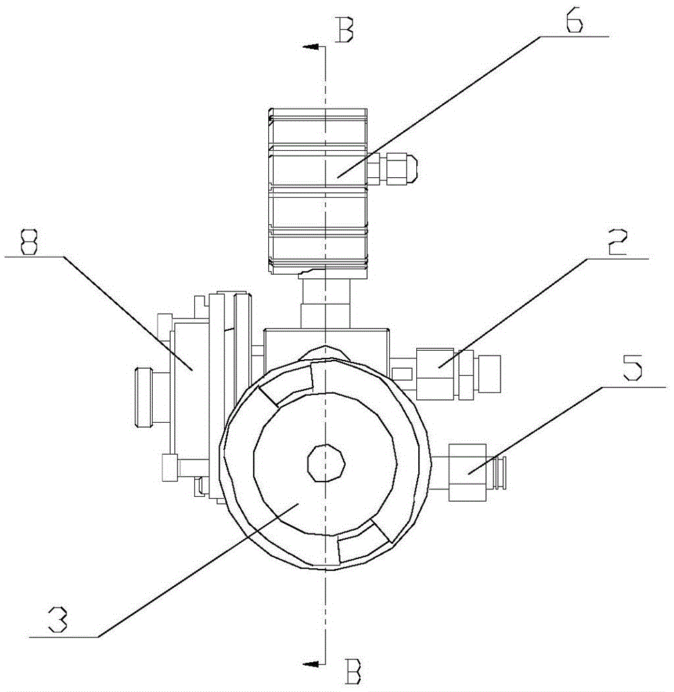
[0021] Such as figure 1 , figure 2 , image 3 , Figure 4 As shown, the present invention includes a motor, a booster pump and a detection device, the motor is connected to the booster pump, and the detection device includes a housing 1 and water inlet A2, water inlet B3, Water outlet 5, digital display pressure controller 6, detection port A7 and detection port B8, wherein water inlet A2 is connected to the outlet of the booster pump, water inlet B3 is connected to the fire hydrant through a fire hose, and water outlet 5 is connected to the booster pump. The water inlet of the pressure pump is connected. There are two detection terminals, among which the detection terminal A7 is used to detect the burst pressure of the hose (the main detection indicators are: working pressure, test pressure, and burst pressure), and the detection terminal B8 is used to detect the overall performance of the fire hose and the interface (in Whether the fire-fighting hose leaks under the pre...


PUM


Abstract

The invention discloses an onsite fire hose detection device quick in water filling and pressure stabilizing. The onsite fire hose detection device comprises a motor, a booster pump and a detector, the detector comprises a shell, a detection end A, a detection end B, a digital display pressure controller, a water inlet end A, a water inlet end B and a water outlet end, the detection end A positioned on the shell is used for detecting a burst pressure of a fire hose, and the detection end B is used for detecting integral performances of the fire hose and connectors. The shell internally comprises a chamber A and a chamber B, the water inlet end B and the water outlet end connected with a water inlet of the booster pump are communicated with the chamber A, the detection end A and the water inlet end A connected with a water outlet of the booster pump are communicated with the chamber B, and a check valve is arranged between the chamber A and the chamber B. When the water pressure in the chamber B is larger than that in the chamber A, the check valve is turned off, and the digital display pressure controller is connected to the chamber B to control starting of the motor through a contactor. The onsite fire hose detection device is convenient and quick in detection and accurate in detection result and capable of quickly filling the fire hose with water within 1min and has a function of pressure maintaining.

Description

technical field [0001] The invention relates to an on-site detection device for a fire-fighting hose, in particular to an on-site detection device for a fire-fighting hose capable of rapid water filling and voltage stabilization, and belongs to the field of fire safety detection devices. Background technique: [0002] The existing fire hose on-site detection device has the following defects during use: 1) It cannot quickly fill the fire hose with water. According to the "Fire Hose" GB6246-2011 testing standard, it is required to fill the 1.2m fire hose within 1 minute. The water hose, and the previous detection device has only one water inlet, that is, the water outlet of the booster pump. The flow and velocity of the booster pump determine the water filling speed of the fire hose, so most of them fail to meet the detection standards In addition, the water inlet of the previous device was a tap water pipe, and the fire hydrant was not used to enter the water, so the flow rat...

Claims


Application Information

Patent Timeline
IPC IPC(8): G01N3/12
CPCG01N3/12
Inventor 李明轩卢国建刘军军梅秀娟熊筠胡忠日
Owner 应急管理部四川消防研究所
Why Eureka
Try Eureka