
Video control system and method of LED color difference compensation

A technology of video control and chromatic aberration, applied to instruments, static indicators, etc., can solve problems such as difficult implementation and complicated process

Active Publication Date: 2016-05-25
DALIAN JISITE TECH
View PDF14 Cites 0 Cited by
  • Summary
  • Abstract
  • Description
  • Claims
  • Application Information

AI Technical Summary

Problems solved by technology

like figure 1 As shown, the process of this method of chromatic aberration compensation is relatively complicated, and it is relatively difficult to realize

Method used


Image

  • Video control system and method of LED color difference compensation
  • Video control system and method of LED color difference compensation
  • Video control system and method of LED color difference compensation

Examples


Embodiment Construction

[0038] In order to make the purpose, technical solutions and advantages of the embodiments of the present invention clearer, the technical solutions in the embodiments of the present invention will be clearly and completely described below in conjunction with the drawings in the embodiments of the present invention. Obviously, the described embodiments It is a part of embodiments of the present invention, but not all embodiments. Based on the embodiments of the present invention, all other embodiments obtained by persons of ordinary skill in the art without creative efforts fall within the protection scope of the present invention.

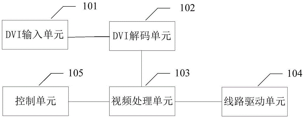
[0039] figure 1 It is a schematic structural diagram of the video control system for LED chromatic aberration compensation of the present invention, as figure 1 As shown, the system of this embodiment may include:

[0040] DVI input unit 101, DVI decoding unit 102, video processing unit 103, line driver unit 104 and control unit 105;

[0041] T...


PUM


Abstract

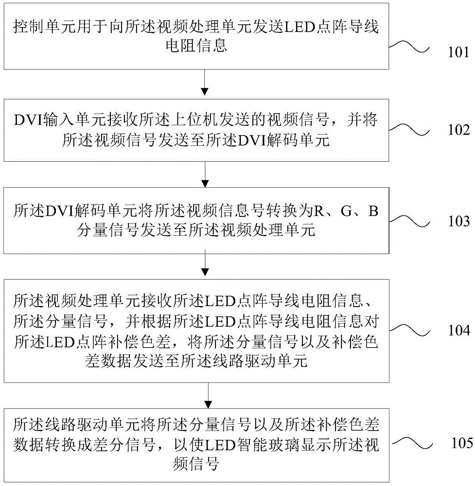
The present invention provides a video control system and method of LED color difference compensation. The system comprises a DVI input unit which is connected to a host machine through a DVI cable and is used for receiving the video signal sent by the host machine and sending the video signal to a DVI decoding unit, the DVI decoding unit, a video processing unit, a line driving unit and a control unit. The control unit is used for sending LED lattice conductive wire resistance information to the video processing unit. The DVI decoding unit is used for converting the video signal into R, G, and B component signals and sending the R, G, and B component signals to the video processing unit. The video processing unit is used for receiving the LED lattice conductive wire resistance information and the component signals, carrying out color difference compensation on the LED lattice according to the LED lattice conductive wire resistance information, and sending the component signals and color difference compensation data to the line driving unit. The line driving unit is used for converting the component signals and the color difference compensation data into differential signals. The LED video color difference compensation control is realized by the invention.

Description

technical field [0001] The embodiment of the present invention relates to the technical field of LED smart glass display, and in particular to a video control system and method for LED color difference compensation. Background technique [0002] At present, the smart glass display screen realizes the playback of images and videos by controlling the LED dot matrix embedded in the glass, which has a more beautiful display effect and a wider application range than the existing display screens. The LED display screen is a flat display screen composed of dot matrix modules or pixel units composed of light-emitting diodes. It integrates a variety of technologies, including computer technology, communication technology, graphics technology, optoelectronic technology, and large-scale integrated circuit technology. With the advantages of long viewing distance, it has been widely used in various fields. The LED large screen system is mainly composed of PC, controller, driver, video ...

Claims


Application Information

Patent Timeline
Patent Type & Authority Applications(China)
IPC IPC(8): G09G3/32
CPCG09G3/32
Inventor 熊木地隋志坤吴志诚刘耀崔建军
Owner DALIAN JISITE TECH
Learn More