Eureka AIR delivers breakthrough ideas for toughest innovation challenges, trusted by R&D personnel around the world.

A motor control unit

A control unit and motor technology, which is applied in the direction of AC motor control, electrical components, control systems, etc., can solve the problems of increased cost, complex control panel structure, and difficulty in effectively utilizing control panel space, and achieves the effect of simple cost.

Inactive Publication Date: 2016-05-25
SANYO DENKI CO LTD
View PDF7 Cites 0 Cited by
  • Summary
  • Abstract
  • Description
  • Claims
  • Application Information

AI Technical Summary

Problems solved by technology

Therefore, it is difficult to use the space efficiently due to the use of space inside and outside the control panel
In addition, due to the high price of the heating plate itself, the cost increases
[0007] In addition, in the technical solution disclosed in Japanese Patent Laid-Open Publication No. Hei 5-260763, since a plurality of metal plates are used, the cost of the metal plate increases
In addition, in the technical solution disclosed in Japanese Patent Laid-Open Publication No. Hei 6-284522, the structure of the control panel for natural cooling is complicated
Additionally, motor controls mounted on the back of the control panel use a larger amount of space on the back of the control panel
Therefore, it is difficult to effectively use the space in the control panel

Method used


Image

  • A motor control unit
  • A motor control unit
  • A motor control unit

Examples


Embodiment Construction

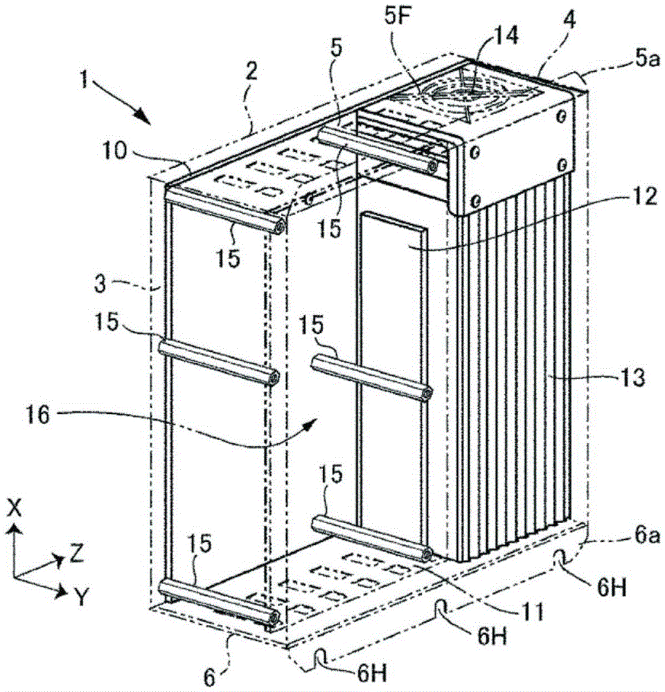
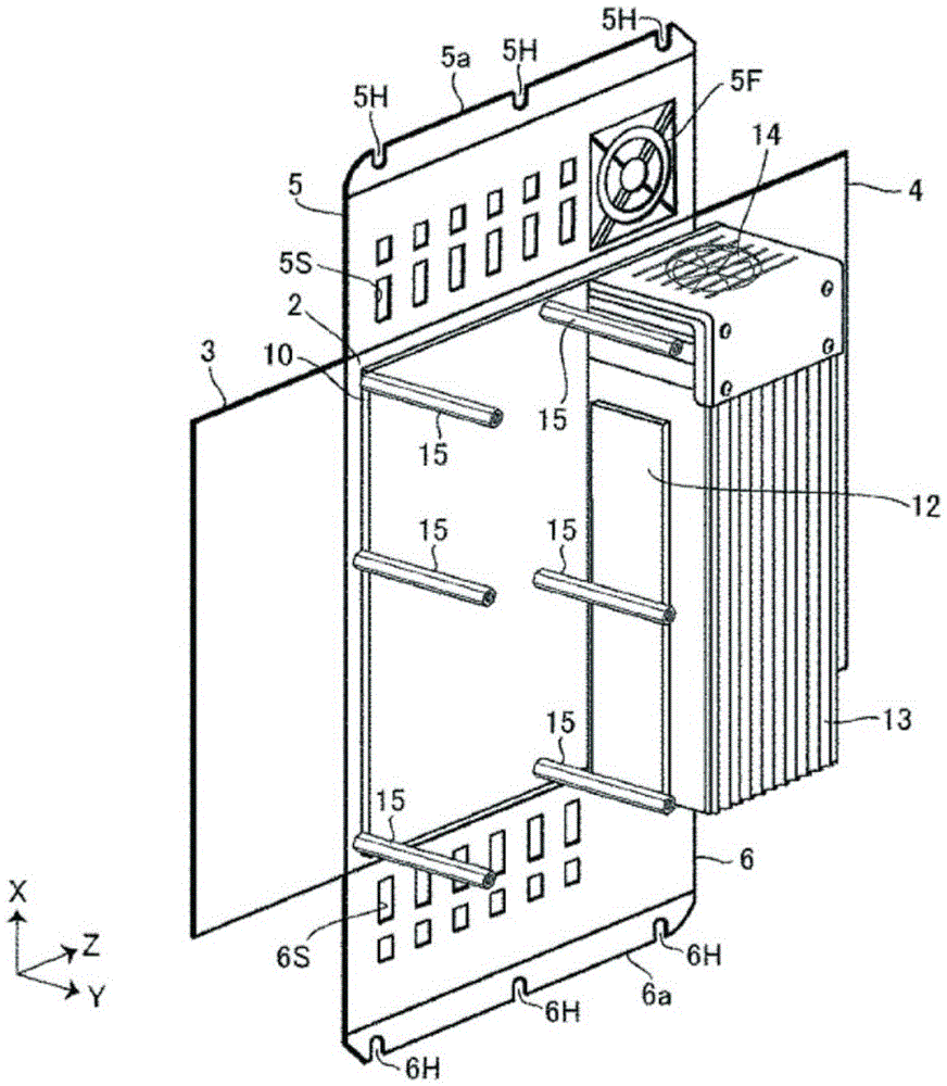
[0046] figure 1 It is a partially see-through perspective view of the motor control unit 1 according to the embodiment of the present invention. figure 2 It is a perspective view of the motor control unit 1 in an open state. In the paper, the X axis represents the vertical direction of the motor control unit 1 , the Y axis represents the depth (thickness) direction of the motor control unit 1 , and the Z axis represents the width direction of the motor control unit 1 .

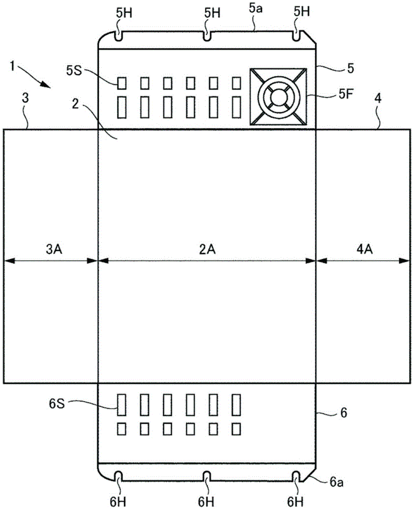
[0047] The box body of the motor control unit 1 includes: a base plate portion 2 , a left plate portion 3 , a right plate portion 4 , a top plate portion 5 and a bottom plate portion 6 . The left side plate 3 and the right side plate 4 are substantially perpendicular to the surface of the base plate 2 and connected to the left and right sides of the base plate 2 , respectively. The top plate portion 5 is substantially perpendicular to the surface of the base plate portion 2 and is connected to the upper sid...


PUM


Abstract

The invention provides a motor control unit which is simple and low in cost. The inner space and the outer space of a control panel provided with the motor control unit can be effectively utilized. The motor control unit comprises a box body in the shape of a cuboid. The box body comprises a base plate part, and a left side plate part, a right side plate part, a top plate part and a bottom plate part which are substantially perpendicular to the surfaces of the base plate part and connected to the left side, the right side, the upper side and the lower side of the base plate part. The box body has an open part as the open surface. The box body is arranged on the control panel which is dimensioned to containing the box body. The box body comprises a semiconductor element for power supply to control target devices, and a heat dissipation part (heat dissipation fins or a fan) for dissipating heat of the heating semiconductor element. When the motor control unit is installed on the control panel, the heat dissipation part is arranged on the plate side of the control panel.

Description

technical field [0001] The invention relates to the structure of a motor control unit. Background technique [0002] A motor control unit that controls a motor or the like has a housing including a main circuit board and a control circuit board. On the above-mentioned main circuit board are mounted large-scale components that generate large amounts of heat, such as semiconductor elements constituting converters and inverters, and electrolytic capacitors. In addition, circuit components for controlling the inverter, such as a CPU and an IC, are mounted on the control circuit board. [0003] The case of the motor control unit includes a metal plate that supports the main circuit board and the control circuit board. In addition, ECUs usually include heat sinks and cooling fans. The heat sink and the cooling fan cool circuit components such as semiconductor elements constituting a converter mounted on a substrate, semiconductor elements constituting an inverter mounted on a s...

Claims


Application Information

Patent Timeline
IPC IPC(8): H02P23/00
Inventor 井出勇治押森卓男小池宏明
Owner SANYO DENKI CO LTD
Why Eureka
Eureka Blog
Learn More