

Oil supply type compressor
一种压缩机、供油的技术,应用在旋转活塞式机械、机械设备、机器/发动机等方向,能够解决电动机负担增大、压缩空气供给量不足等问题,达到避免起动迟滞、缩短压力降低时间的效果
- Summary
- Abstract
- Description
- Claims
- Application Information
AI Technical Summary
Problems solved by technology
Method used
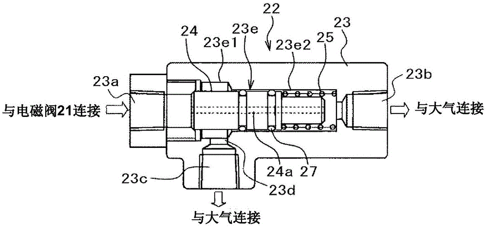
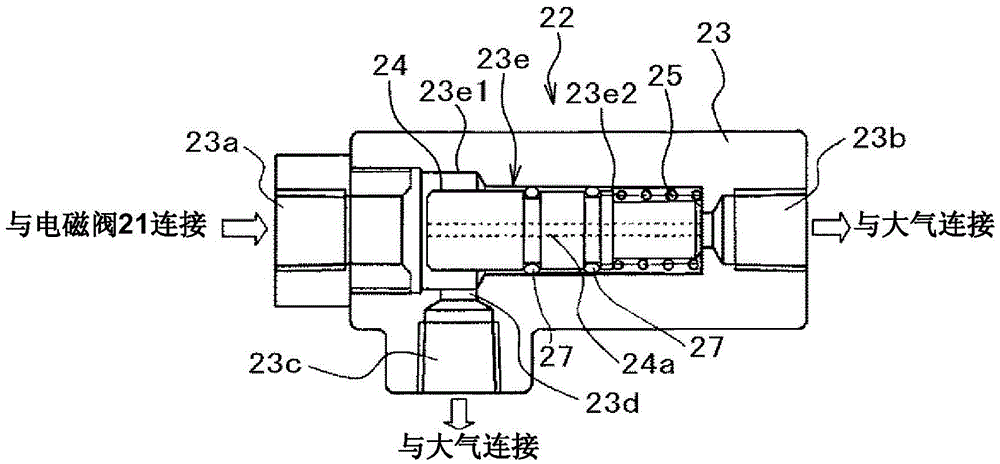
Image

Examples
Embodiment 1
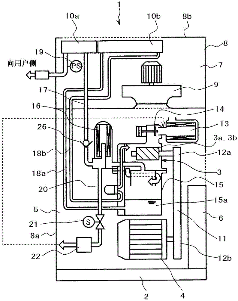
[0041] For the embodiment 1 of the oil-supply compressor of the present invention, take the situation applied to the oil-supply screw compressor as an example, use Figure 1 ~ Figure 4 Be explained.
[0042] according to figure 1 , to describe the overall structure of the oil-supplied screw compressor of the first embodiment.
[0043] figure 1 The illustrated oil-supply screw compressor (hereinafter also simply referred to as a compressor) 1 is a device for producing compressed air, and is configured as a package type. This package type oil supply type screw compressor 1 has a base 2 as a base and a package 8 provided on the base 2 , and the inside of the package 8 is divided into a lower machine room 5 and an upper cooling room 7 . The package 8 is constituted by soundproof covers 8a, 8b for suppressing the propagation of noise to the outside of the machine.
[0044] In the above-mentioned machine room 5, a compressor main body 3 for producing compressed air, a motor 4 fo...
PUM
 Abstract
Description
Claims
Application Information