Automatic steel bar feeding device and cutting-off machine

An automatic feeding and bar material technology used in cutting devices and cutting machines. ,Feeding device, in the field of automatic steel bar feeding device, it can solve the problems of inability to use cutting machine, surface damage of steel bar, high labor intensity, etc., to avoid scratches on the surface of steel bar, high shear force, and increase the number of shears.

Active Publication Date: 2016-06-01
宁国市永鼎知识产权运营有限公司
View PDF9 Cites 4 Cited by
  • Summary
  • Abstract
  • Description
  • Claims
  • Application Information

AI Technical Summary

Problems solved by technology

All the existing cutting machines need manual feeding, which has the problem of high labor intensity
[0004] Known by consulting the literature, although there is an automatic feeding device for steel rods on record in the literature, such as the automatic feeding device for bars (CN201030440Y) recorded in the Chinese patent literature, and the automatic steel rod feeding machine (CN201214122Y); but due to the poor versatility of the above-mentioned feeding device , It is easy to cause problems such as damage to the surface of the steel bar and cannot be used in the cutting machine

Method used


Image

  • Automatic steel bar feeding device and cutting-off machine
  • Automatic steel bar feeding device and cutting-off machine
  • Automatic steel bar feeding device and cutting-off machine

Examples


Embodiment Construction

[0026] The following are specific embodiments of the present invention and in conjunction with the accompanying drawings, the technical solutions of the present invention are further described, but the present invention is not limited to these embodiments.

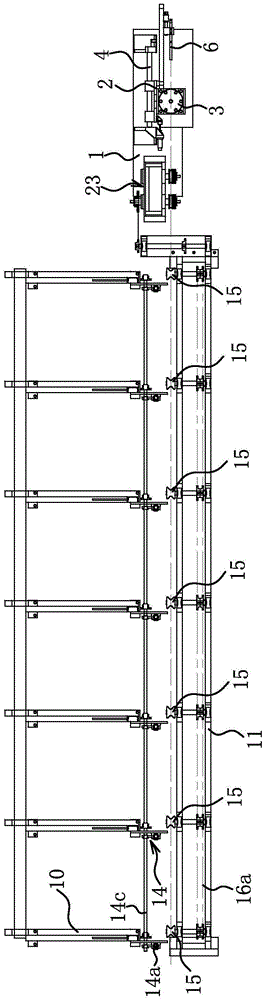
[0027] The steel bar automatic feeding device comprises a bar storage rack 10 and a bar delivery rack 11 .

[0028] The bar stock storage rack 10 has a material placing platform 10a arranged obliquely. The bar storage rack 10 includes a storage base frame 10b and a bar bracket 10c; the upper surface of the bar bracket 10c is an adjustable inclination angle of the material placing table 10a. One side edge of the bar bracket 10c is hinged to the storage base 10b, and the other side of the bar bracket 10c is connected to the storage base 10b through multiple sets of screw lifters 10d; specifically , the body of the screw lifter 10d is hinged with the storage base frame 10b, and the screw mandrel of the screw lifter 10d is hi...


PUM


Abstract

The invention provides an automatic steel bar feeding device and a cutting-off machine and belongs to the technical field of machines. The problems that an existing feeding device is poor in universality and prone to causing damage to the surfaces of steel bars are solved. The automatic steel bar feeding device comprises a bar material storage frame and a bar material conveying frame arranged on one side of the bar material storage frame, wherein the bar material conveying frame is rotationally connected with a plurality of conveying wheels for carrying workpieces; a stop plate used for limiting the workpieces from sliding downwards is fixed to the bar material storage frame, and the upper end surface of the stop plate is an inclined surface; and a pushing structure capable of pushing the workpiece abutting against the stop plate to the upper end surface of the stop plate is arranged below a material storage tabletop. The automatic steel bar feeding device is used for conveying steel bars, and the steel bars naturally slide downwards until being stopped by the stop plate; the pushing structure pushes one steel bar abutting against the stop plate upwards, and the steel bar slides downwards into one conveying wheel along the upper end surface of the stop plate; the conveying wheels have friction with the steel bars and drive the steel bars to move forwards in the axial direction, and automatic conveying of the steel bars is realized.

Description

technical field [0001] The invention belongs to the technical field of machinery, and relates to a feeding device, in particular to an automatic feeding device for steel rods. [0002] The invention belongs to the technical field of machinery, and relates to a cutting device, in particular to a cutting machine. Background technique [0003] In metalworking, straight steel rods are cut into short bars to desired lengths for subsequent processing, such as rivets, bolts, pins and shafts. All the existing cutting machines need manual feeding, which has the problem of high labor intensity. [0004] Known by consulting the literature, although there is an automatic feeding device for steel rods on record in the literature, such as the automatic feeding device for bars (CN201030440Y) recorded in the Chinese patent literature, and the automatic steel rod feeding machine (CN201214122Y); but due to the poor versatility of the above-mentioned feeding device , It is easy to cause prob...

Claims


Application Information

Patent Timeline
Patent Type & Authority Applications(China)
IPC IPC(8): B21D28/02B21D43/02B21D43/20B21D28/14
CPCB21D28/02B21D28/14B21D43/006B21D43/20
Inventor 姚章华
Owner 宁国市永鼎知识产权运营有限公司
Why Eureka
Try Eureka