
Contact tube positioning tool and contact tube machining method

A technology for positioning tooling and processing methods, applied in metal processing, metal processing equipment, conductors, etc., can solve the problems of difficulty in on-site debugging, affecting the power supply of the power grid, and unqualified three-phase products in the same period, so as to overcome the dependence of large-scale equipment. Effect

Active Publication Date: 2016-06-01
HENAN PINGGAO ELECTRIC +2
View PDF6 Cites 5 Cited by
  • Summary
  • Abstract
  • Description
  • Claims
  • Application Information

AI Technical Summary

Problems solved by technology

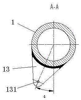
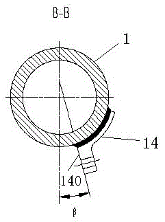
If the angle between the support 13 and the ball frame 14 is out of tolerance (out of tolerance means that the product dimensions exceed the tolerance range specified in the product standard), it will affect the closing angle of the product, resulting in unqualified synchronism of the three-phase product, affecting Normal grid power supply brings difficulties to on-site commissioning

Method used


Image

  • Contact tube positioning tool and contact tube machining method
  • Contact tube positioning tool and contact tube machining method
  • Contact tube positioning tool and contact tube machining method

Examples


Embodiment Construction

[0028] The embodiments of the present invention will be further described below in conjunction with the drawings.

[0029] Specific embodiments of the conductive tube positioning tool of the present invention, such as Figure 4 to Figure 12 As shown, the conductive tube positioning tooling includes a workbench 2, on which a tooling positioning piece is installed. The tooling positioning piece includes an end positioning plate 8, a horizontal pressing plate 51, an intermediate pressing plate 52, a support positioning frame 3, a ball frame positioning frame 4 and V-block 7. The workbench 2 is provided with a T-shaped groove 21 extending in the left and right direction. The bottom of the support positioning frame 3, the ball rack positioning frame 4 and the V-shaped block 7 are all provided with a bump structure, and they are installed in the T-shaped block through the bump structure. Slot 21. End positioning plates 8 are fixed on the end surfaces of the left and right ends of the...


PUM


Abstract

The invention relates to a contact tube positioning tool and a contact tube machining method. The contact tube positioning tool comprises a workbench, wherein a tool positioning piece is assembled on the workbench and comprises horizontal press plates for horizontally pressing main contact finger mounting planes of end contact tubes, a support positioning frame for mounting a support and a ball rack positioning frame for mounting a ball rack, the support positioning frame comprises a support positioning hole coaxially fixed with a support mounting hole, and the ball rack positioning frame comprises a ball rack positioning surface fit with a ball rack mounting surface. The main contact finger mounting planes of the end contact tubes are kept horizontal by the horizontal press plates, reference is provided for assembly of a ball rack and a support, the support positioning frame and the ball rack positioning frame are assembled on the workbench, positions where the support mounting hole and the ball rack mounting surface are located are determined respectively by the aid of the support positioning hole and the ball rack positioning surface, and angle requirements of the support and the ball rack during positioning are guaranteed, so that a contact tube is positioned and meets the final product use requirement.

Description

Technical field [0001] The invention relates to a conductive tube positioning tool and a conductive tube processing method. Background technique [0002] With the continuous development and growth of the national power market, high-voltage and high-current power transmission and transformation products have become the leading products in the power market, and the demand for high-voltage isolation switches is increasing. The quality of the conductive tube determines the performance of the whole product and plays an important role in opening and closing. At present, the GW27 series of isolation switch products are used in large quantities in power stations, and users have higher and higher requirements for their current capacity. The entire conductive circuit of the isolation switch is designed to increase the capacity, and the length of the conductive tube is longer, often exceeding 6 Therefore, the conductive tube is usually manufactured by the method of first segmented processi...

Claims


Application Information

Patent Timeline
Patent Type & Authority Applications(China)
IPC IPC(8): B23K37/053
CPCB23K37/053B23K2101/38
Inventor 李宇鹏庞庆平王亚辉张任王赏樊俊超胡广林夏立国
Owner HENAN PINGGAO ELECTRIC
Learn More