Clutch hub demounting tool provided with handle sleeve and used for remanufacturing of automatic transmission
A technology for automatic transmissions and clutch hubs, applied in the manufacture of tools, hand-held tools, etc., can solve the problems of clutch hub damage, loud noise, inconvenience, etc., and achieve the effect of not easy noise, low noise, and good reliability
- Summary
- Abstract
- Description
- Claims
- Application Information
AI Technical Summary
Problems solved by technology
Method used
Image

Examples
Embodiment 1
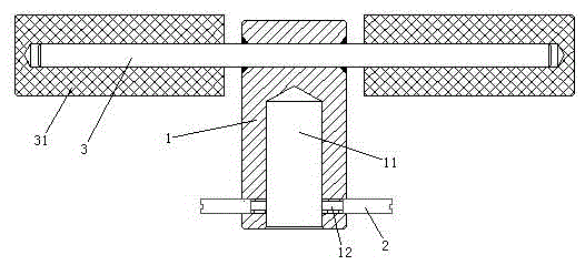
[0024] Embodiment one, see figure 1 , a clutch hub removal tool provided with a handle glove for remanufacturing an automatic transmission, including a pull rod 1 . The upper end of the pull rod 1 is provided with a grip rod 3 . Grip bar 3 has two. Two holding rods 3 are symmetrically distributed on both sides of the pull rod 1 . 3 sets of grip bars are provided with handle gloves 31 . The handle glove 31 is a rubber sheath. The handle glove 31 is detachably sheathed on the handle bar 3 . The end surface of the lower end of the pull rod 1 is provided with an accommodating hole 11 which can be sleeved on the rotating shaft. The wall of the receiving hole 11 is provided with a through hole 12 that can be aligned with the slot when the rotating shaft is inserted into the receiving hole. The through hole 12 is a threaded hole. A bayonet pin 2 that can be inserted into the bayonet is screwed into the through hole 12 . Bayonet 2 is a jacking bolt.
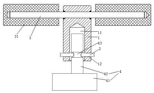
[0025] see figure 2 Th...
Embodiment 2
[0027] Embodiment two, the difference with embodiment one is:
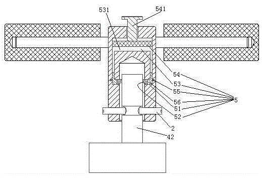
[0028] see image 3 , a clamping and fixing structure 5 is also provided. The clamping and fixing structure 5 includes a sliding hole 51 , a clamping block 52 slidingly and sealingly connected to the sliding hole, a piston chamber 53 , a pressurizing piston 54 slidingly and sealingly connected to the piston chamber, and a heating mechanism 55 . The sliding hole 51 is disposed on a wall of the receiving hole 11 . There are two sliding holes 51 . Two sliding holes 13 are distributed along the circumferential direction of the tie rod 1 . The piston chamber 53 is disposed on the tie rod 1 . There is only one piston chamber 53. The piston chamber 53 is in communication with all the slide holes 51 . The press piston 54 is provided with a press rod 541 . The pressing rod 541 protrudes from the end of the tie rod 1 . A closed cavity 531 is formed between the pressurizing piston 54 and the clamping block 52 . A ti...
Embodiment 3
[0031] Embodiment three, the difference with embodiment two is:
[0032] see Figure 4, An elastic force adjustment mechanism 8 is provided between the grip bar 3 and the handle cover 31 . The elastic force adjustment mechanism 8 includes a base pipe 81 , a clamping layer 82 and a preload adjustment structure 83 . The base tube 81 is sheathed outside the handle bar 3 . The base pipe 81 is passed through the handle glove 31 . The clamping layer 82 is composed of several friction strips 821 . The friction strips 821 are distributed along the circumferential direction of the base pipe 81 . The friction strip 821 is provided with a plurality of slide bars 822 axially distributed along the radial extension of the base pipe. The sliding rod 822 slides through the base tube 81 . The inner end of the sliding rod 822 is provided with a third spring 823 . The third spring 823 drives the friction strip to abut against the handle glove 31 through the slide bar. The outwardly movin...
PUM
 Abstract
Description
Claims
Application Information