Press roll structure

A pressure roller and roller body technology, applied in the field of pressure roller structure, can solve the problems of damage to the cutting machine, hitting the edge of the cutting machine, etc.

Inactive Publication Date: 2016-06-01
JIANGYIN LICHNEG MACHINERY CO LTD
View PDF0 Cites 2 Cited by
  • Summary
  • Abstract
  • Description
  • Claims
  • Application Information

AI Technical Summary

Problems solved by technology

[0002] When the composite board is being cut, in order to make the cutting taste good, the composite board will be pressed tightly with a pressure roller, but after the board is cut and separated into two pieces, the distance between the two boards is very small, if you continue to advance along a straight line, When the plate falls, it is easy to hit the cutting machine and be damaged, or hit the edge of the cutting machine

Method used


Image

  • Press roll structure

Examples


Embodiment Construction

[0008] All features disclosed in this specification, or steps in all methods or processes disclosed, may be combined in any manner, except for mutually exclusive features and / or steps.

[0009] Any feature disclosed in this specification (including any appended claims, abstract and drawings), unless expressly stated otherwise, may be replaced by alternative features which are equivalent or serve a similar purpose. That is, unless expressly stated otherwise, each feature is one example only of a series of equivalent or similar features.

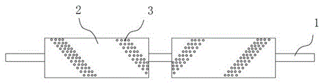
[0010] like figure 1 The pressure roller structure shown includes a main shaft 1, on which two roller bodies 2 are symmetrically arranged, and there is a gap between the two roller bodies 2, and friction points are distributed on each roller body 2 in a band shape 3. Each friction point 3 is a raised rubber head, and the angle between the friction point 3 and the surface of the roller body 2 is 45°, and the friction points on the two roller b...


PUM


Abstract

The invention discloses a press roll structure which comprises a main shaft. Two roll bodies are arranged at the two ends of the main shaft, and friction points are symmetrically distributed on the two roll bodies in a strip shape. After a plate is cut, the roll bodies press the plate and drive the plate to move, the plate is rubbed by the friction points on the roll bodies, and therefore the moving direction is changed, and two pieces formed by cutting the plate are separated.

Description

technical field [0001] The invention relates to a pressure roller structure, in particular to a pressure roller structure used on a composite board cutting machine. Background technique [0002] When the composite board is being cut, in order to make the cutting taste good, the composite board will be pressed tightly with a pressure roller, but after the board is cut and separated into two pieces, the distance between the two boards is very small, if you continue to move forward in a straight line, When the plate falls, it is easy to hit the cutting machine and be damaged, or hit the edge of the cutting machine. Contents of the invention [0003] The invention relates to a pressing roller structure, which can change the moving direction of the cut plate. [0004] In order to achieve this purpose, the structure adopted in the present invention is: a pressure roller structure, including a main shaft, two roller bodies are symmetrically arranged on the main shaft, there is a...

Claims


Application Information

Patent Timeline
Patent Type & Authority Applications(China)
IPC IPC(8): B26D7/02B26D7/32
CPCB26D7/025B26D7/32
Inventor 朱云卫
Owner JIANGYIN LICHNEG MACHINERY CO LTD
Why Eureka
Try Eureka