Automatic spraying equipment for motor paint spraying and working method of automatic spraying equipment

An automatic spraying and equipment technology, which is applied in the direction of cleaning methods using gas flow, chemical instruments and methods, spray booths, etc., can solve the problems of low painting efficiency, paint dust pollution of the surrounding environment, etc., and achieve the effect of convenient painting

Active Publication Date: 2021-04-20
无锡华庄电机有限公司
View PDF6 Cites 1 Cited by
  • Summary
  • Abstract
  • Description
  • Claims
  • Application Information

AI Technical Summary

Problems solved by technology

[0005] Aiming at the deficiencies of the prior art, the present invention discloses an automatic spraying equipment for motor spraying to solve the problems in the prior art that the paint dust generated by manual painting seriously pollutes the surrounding environment and the painting efficiency is low.

Method used


Image

  • Automatic spraying equipment for motor paint spraying and working method of automatic spraying equipment
  • Automatic spraying equipment for motor paint spraying and working method of automatic spraying equipment
  • Automatic spraying equipment for motor paint spraying and working method of automatic spraying equipment

Examples


Embodiment Construction

[0036] The specific implementation of this embodiment will be described below in conjunction with the accompanying drawings.

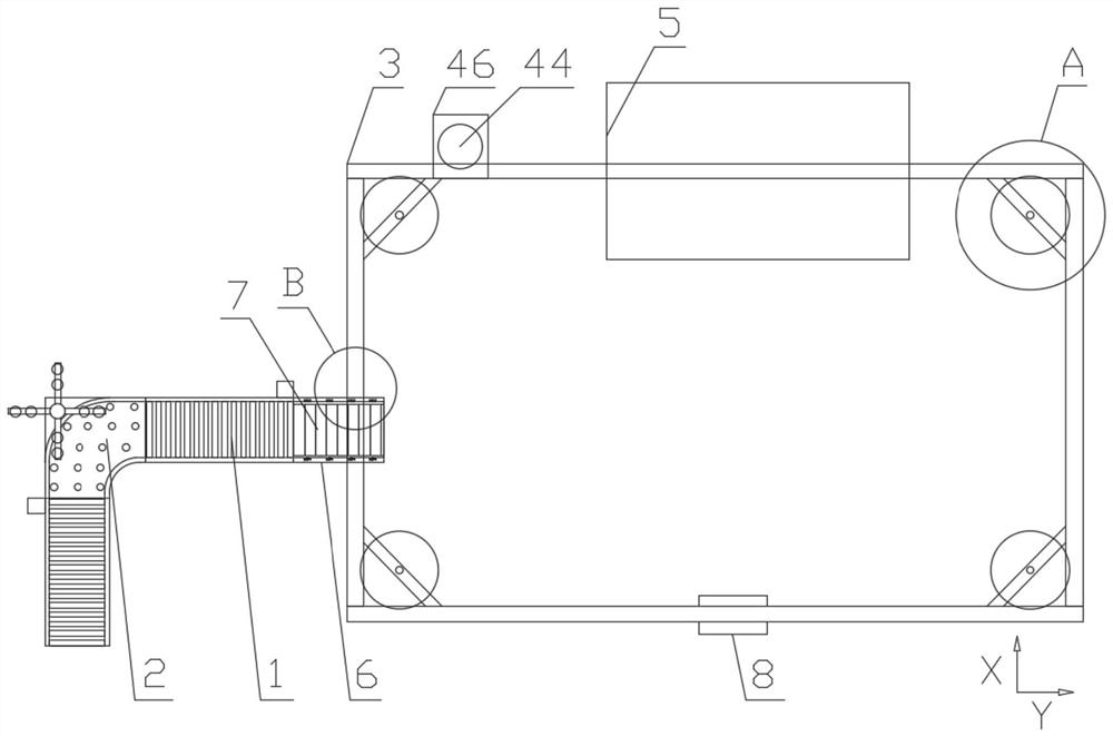
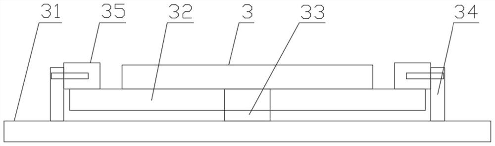
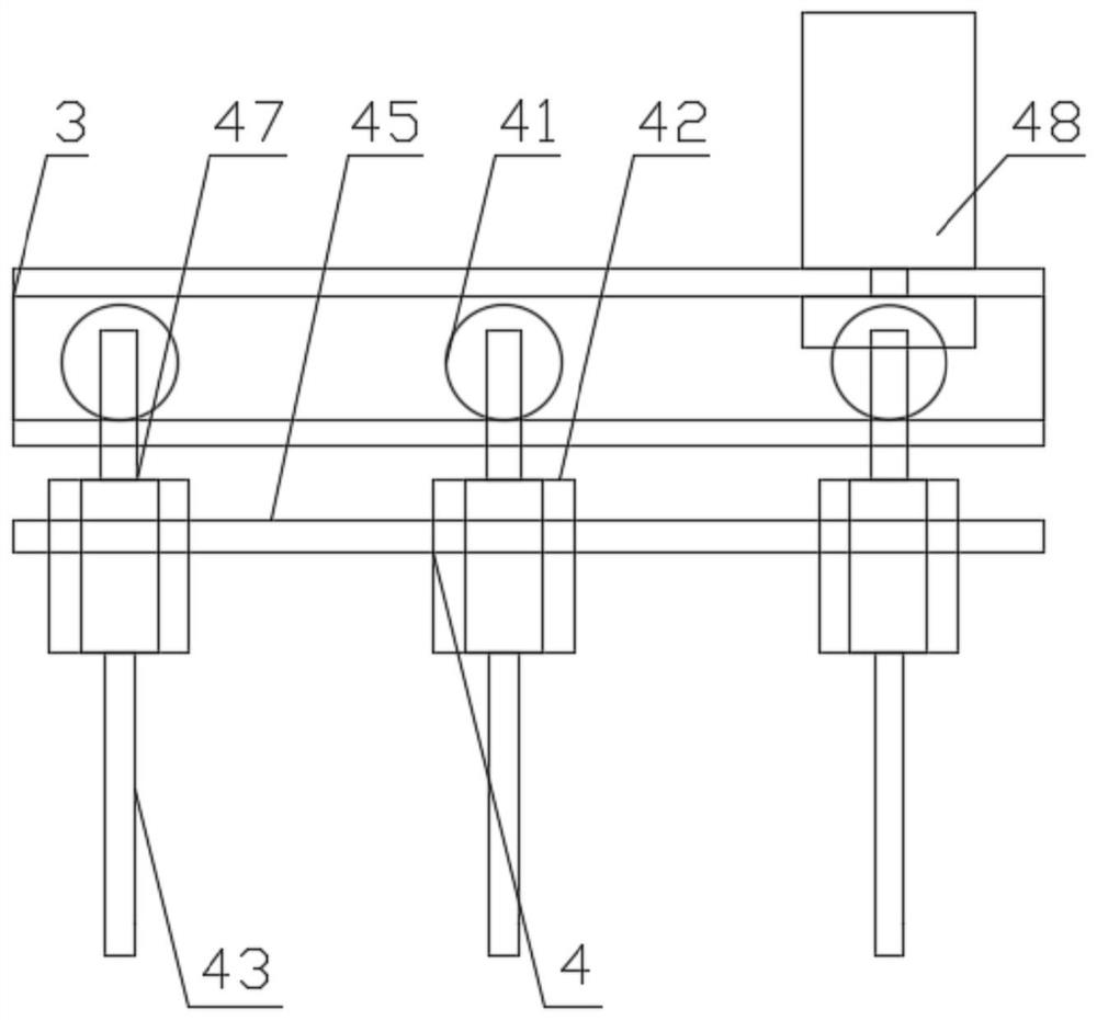
[0037] figure 1 It is a top view structure diagram of the present invention. figure 2 for figure 1 Schematic diagram of the structure at A. image 3 for figure 1 The left view of the structure at B in the center. Figure 4 It is a structural schematic diagram of the conveying mechanism of the present invention. Figure 5 It is a top structural view of the corner mechanism of the present invention. Image 6 It is a structural schematic diagram of the lifting mechanism of the present invention. Figure 7 It is a top view structure diagram of the painting device of the present invention. combine figure 1 , figure 2 , image 3 , Figure 4 , Figure 5 , Image 6 , Figure 7 and Figure 8 As shown, the invention discloses an automatic spraying equipment and working method for motor spraying. The direction of X in the figure is the front end...


PUM


Abstract

The invention relates to automatic spraying equipment for motor paint spraying and a working method of the automatic spraying equipment. The automatic spraying equipment is characterized by comprising a paint spraying device, a guide rail frame, a plurality of conveying mechanisms for moving motors, corner mechanisms for moving the motors to the adjacent conveying mechanisms, a moving mechanism for moving the motors along the guide rail frame, and a lifting mechanism for pushing the motors to get close to the moving mechanism; the corner mechanisms are arranged between the adjacent conveying mechanisms; the guide rail frame penetrates through the paint spraying device; the moving mechanism is movably arranged on the guide rail frame; the motor is hung on the moving mechanism; and the lifting mechanism is arranged between the conveying mechanisms and the moving mechanism. The problems that according to an existing scheme, paint dust generated by manual paint spraying seriously pollutes the surrounding environment, and the paint spraying efficiency is low are solved.

Description

technical field [0001] The invention relates to painting equipment, in particular to an automatic spraying equipment for motor painting and a working method thereof. Background technique [0002] Generally, motors are indispensable parts in daily life. An electric motor is an electrical device that converts electrical energy into mechanical energy and then uses the mechanical energy to generate kinetic energy to drive other devices. Electric motors are generally called motors, which can convert electrical energy into mechanical energy to drive machinery to rotate, vibrate or linearly move, and are widely used in the fields of motion control and electromechanical integration. There are many types of motors. For the basic structure, the composition is mainly composed of a stator and a rotor. The stator is stationary in space, and the rotor can rotate around its axis. There will be a certain air gap between the stator and the rotor to ensure that the rotor can rotate freely....

Claims


Application Information

Patent Timeline
Patent Type & Authority Applications(China)
IPC IPC(8): B05B16/20B05B16/40B05B13/02B08B5/02
Inventor 俞仁龙
Owner 无锡华庄电机有限公司
Why Eureka
Try Eureka