Pallet

a technology of pallets and supports, applied in the field of pallets, can solve the problems of reducing destroying the pallet or damage the support members, and not inserting the tin of the device, so as to reduce the time to load, reduce the damage to the supported products, and increase the strength and durability of the support blocks

Inactive Publication Date: 2005-03-17
CHEP TECH PTY LTD
View PDF50 Cites 30 Cited by
  • Summary
  • Abstract
  • Description
  • Claims
  • Application Information

AI Technical Summary

Benefits of technology

[0005] The support blocks may be formed from a composite material. In at least one embodiment, the composite material may be a combination of a cellular material and at least one thermoplastic resin. The cellular material may be, but is not limited to, a wood species, linen flax shives, bagasse from sugar cane, jute, and bamboo. The thermoplastic resin may be a polypropylene, a polyethylene, or other appropriate thermoplastic resin, or any combination thereof. The composite material may provide increased strength to the support blocks in comparison with support blocks formed from 100 percent wood. The composite material may provide increased wear resistance and, therefore, increased lifespan. The composite material is superior to an all plastic material in that the composite material is nailable, easily machinable, easier to paint, and lighter.
[0007] An advantage of some embodiments of this invention is that the exterior shape of the support blocks form a guide for positioning the lifting members under the top support member of the pallet. Thus, loading a pallet of this invention requires less time to load because time is not lost in aligning the lifting member with the cavities beneath the top support member.
[0008] Another advantage of some embodiments of this invention is that the exterior shape and hard, low friction surface tends to deflect blows received from lifting members striking the support blocks rather than absorbing the forces delivered by the lifting members without redirecting the lifting members. This, in effect, limits damage to products supported by the pallet. In contrast, a hollow plastic block often dents and cups the point of a lifting member upon being struck.
[0009] Yet another advantage of some embodiments of this invention is that the composite material increases the strength and durability of the support blocks, thereby increasing the lifespan of the pallet.

Problems solved by technology

Often times, the tines of these devices are not inserted into the cavities in the correct location beneath the top support members.
Rather, the tines first strike the support members, which either destroys the pallet or damages the support members.
Pallets that are destroyed must be replaced, which often delays delivery schedules and increases costs.
A damaged pallet is weakened and often requires replacement before expiration of a normal lifespan of the pallet.

Method used


Image

  • Pallet
  • Pallet
  • Pallet

Examples


Embodiment Construction

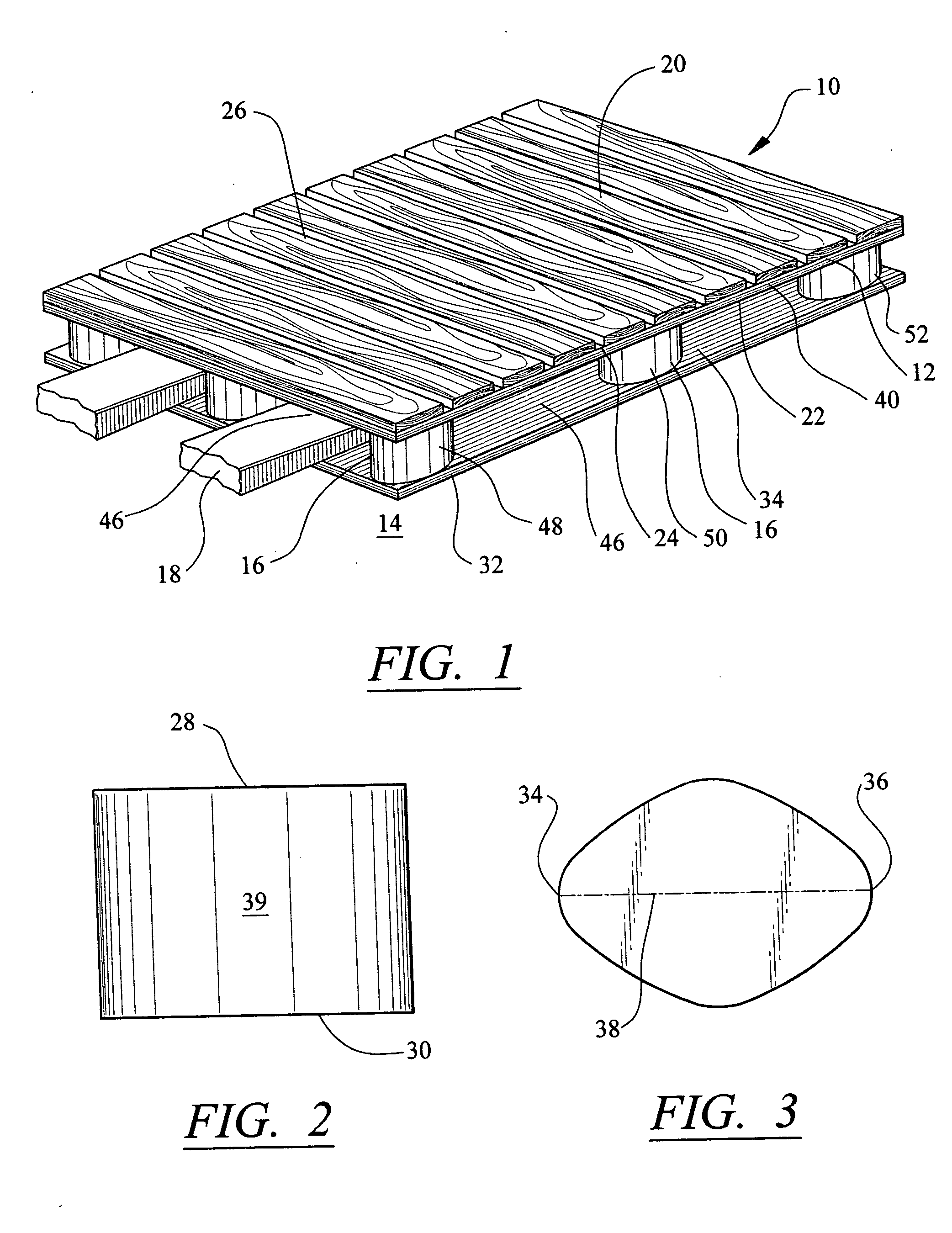
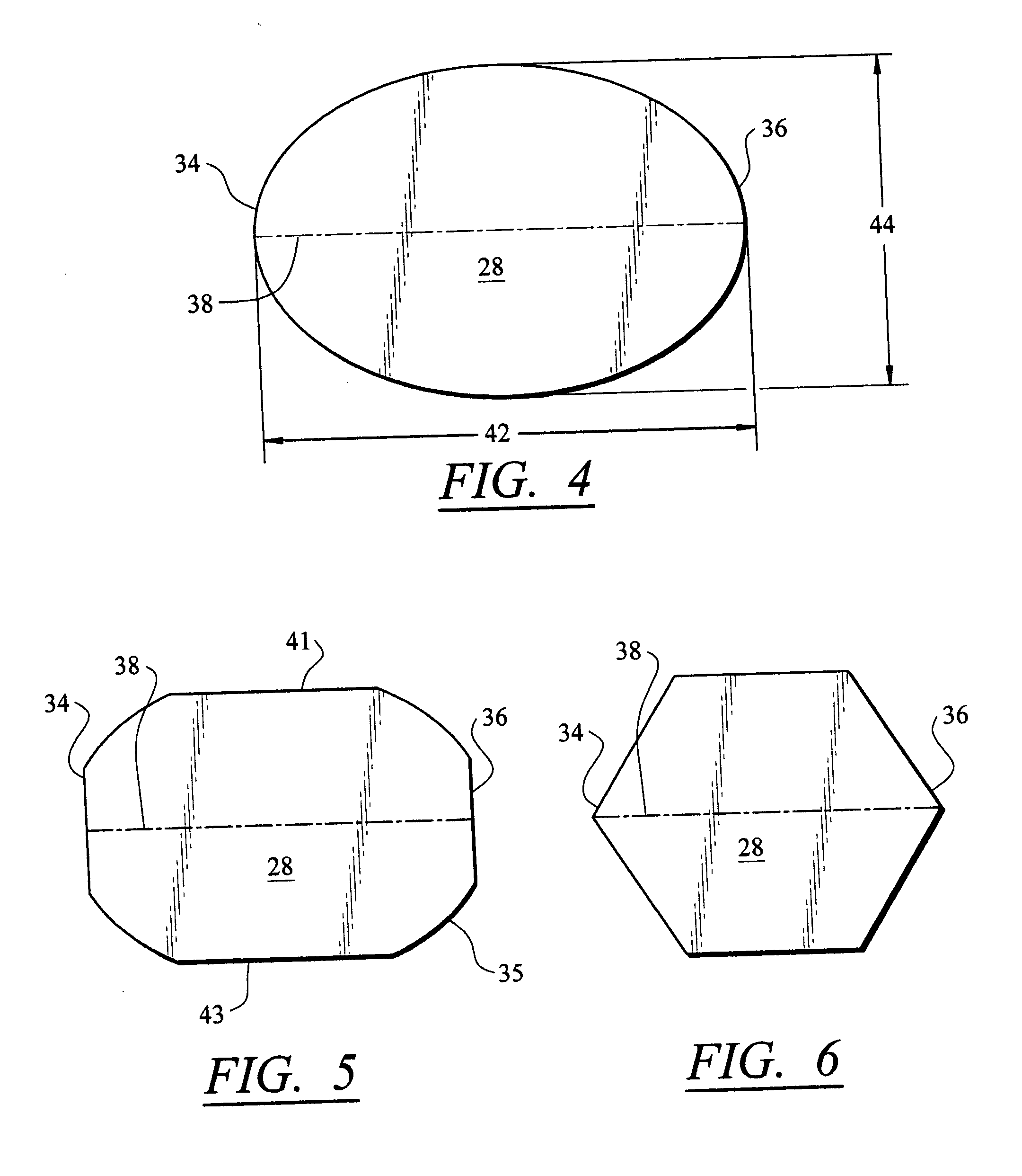
[0022]FIGS. 1-10 illustrate a pallet 10, and related components thereof, configured to support cargo on one or more top support members 12. The top support member 12 is supported above a surface 14 using two or more support blocks 16 positioned to allow lifting members 18 to be placed under the top support member 12 to lift the pallet 10 and the cargo supported by the pallet 10. The top support member 12 may have any suitable shape. In at least one embodiment, as shown in FIG. 1, the top support member 12 may be composed of a generally flat top surface 20 and a bottom surface 22. In other embodiments, top support member 12 may have top surfaces 20 that are not flat. In some embodiments, the top surface 20 may include one or more coatings or other textured materials to prevent cargo from slipping or moving on the top surface 20. In at least one embodiment, as shown in FIG. 1, the top support member 12 may be formed from three cross supports 24 positioned generally parallel to each ot...


PUM


Abstract

A pallet having a top support member for supporting cargo and support elements for supporting the top support member above a surface and for creating one or more cavities for receiving a lifting member for moving the pallet. The support elements may have an oval cross-section for guiding the lifting members into the cavity. The support elements may be formed from a composite material for increased strength and durability.

Description

FIELD OF THE INVENTION [0001] The invention is directed generally to pallets, and more particularly, to cargo pallets having cavities for receiving forklift tines. BACKGROUND [0002] Wood pallets are used to transport and store a variety of different kinds of cargo. Conventional wood pallets are formed from a top support member and a bottom support member separated by a plurality of cavities sized to receive forklift tines. The top and bottom support members are separated by a plurality of wooden support blocks, which are positioned to form the plurality of cavities. The top and bottom support members are often formed from a plurality of 1 inch by 4 inch lumber, and the support blocks are often formed from 2 inch by 4 inch lumber or 4 inch by 4 inch lumber. [0003] During use, forklift tines are inserted into the cavities to lift the pallets. Often times, the tines of these devices are not inserted into the cavities in the correct location beneath the top support members. Rather, the ...

Claims


Application Information

Patent Timeline
Patent Type & Authority Applications(United States)
IPC IPC(8): B65D19/00
CPCB65D19/0081B65D2519/00029B65D2519/00064B65D2519/00099B65D2519/00104B65D2519/00109B65D2519/00835B65D2519/00293B65D2519/00318B65D2519/00343B65D2519/00373B65D2519/00796B65D2519/00273
Inventor LAENDER, BART DENAIDU, VISHNUCOULCHER, RICHARDDILLEN, ANTHONY VANDILLEN, TIEMEN VAN
Owner CHEP TECH PTY LTD
Why Eureka
Try Eureka