
Machining method of hot melting machine

A processing method and hot melt machine technology, applied in the field of parts processing, can solve the problems of high labor intensity in processing parts, and achieve the effect of reducing labor intensity

Inactive Publication Date: 2016-06-01
DONGGUAN GOOD MARK NEW PRECISION TECH CO LTD
View PDF7 Cites 0 Cited by
  • Summary
  • Abstract
  • Description
  • Claims
  • Application Information

AI Technical Summary

Problems solved by technology

[0004] However, since the positioning device is manually positioned through a purely mechanical structure, every time a part needs to be hot-melt connected, the staff needs to disassemble the positioning device, resulting in a relatively high labor intensity for the staff to process the part

Method used


Image

  • Machining method of hot melting machine
  • Machining method of hot melting machine

Examples


Embodiment Construction

[0026] The core of the present invention is to provide a hot-melt machine processing method to reduce the labor intensity of workers processing parts.

[0027] In order to enable those skilled in the art to better understand the technical solutions of the present invention, the present invention will be further described in detail below in conjunction with the accompanying drawings and embodiments.

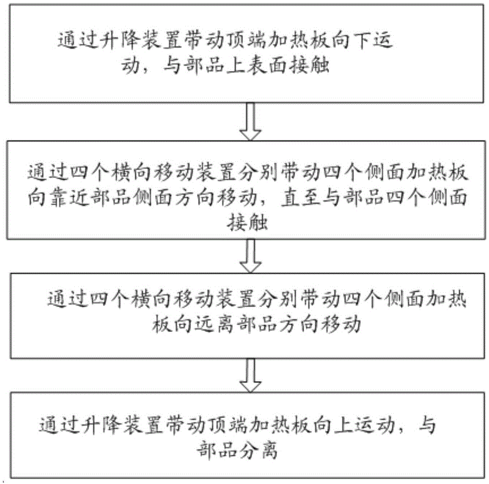
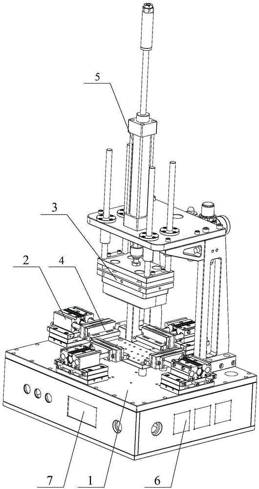
[0028] Please refer to figure 1 and figure 2 , in a specific embodiment, the hot-melt machining method provided by the specific embodiment of the present invention includes the steps of:

[0029] A1) Drive the top heating plate 3 to move downward through the lifting device 5, and contact with the upper surface of the part. Specifically, the lifting device 5 is a hydraulic cylinder, a telescopic rod, or an air cylinder.

[0030] A2) The four lateral moving devices 2 drive the four side heating plates 4 to move toward the side surfaces of the parts until they come into contact w...


PUM


Abstract

The invention discloses a machining method of a hot melting machine. The machining method of the hot melting machine comprises the steps that A1, a top end heating plate is driven by a lifting device to move downwards so as to make contact with the upper surface of a product; A2, four side face heating plates are driven by four transverse movement devices to move in the direction close to the side faces of the product correspondingly till the four side face heating plates make contact with the four side faces of the product; A3, the four side face heating plates are driven by the four transverse movement devices correspondingly to move in the direction away from the product; and A4, the top end heating plate is driven by the lifting device to move upwards so as to be separated from the product. According to the machining method of the hot melting machine, the side face heating plates are driven by the transverse movement devices to make contact with the product, the transverse movement devices stop working after the side face heating plates make contact with the product, and automatic positioning of the product is achieved; compared with the situation that positioning of the product is achieved by manually positioning the side face heating plates by workers, the machining method of the hot melting machine effectively relieves the labor intensity of the workers.

Description

technical field [0001] The invention relates to the technical field of parts processing, in particular to a processing method of a hot-melt machine. Background technique [0002] The hot-melt machine transfers the heat of the heating plate to the welding surface of the upper and lower plastic heating parts through the electric heating method to melt the surface, and then withdraws the heating plate to complete the hot-melt connection of the parts. [0003] Specifically, the traditional hot-melt machine includes a hot-melt mold, a hot-melt positioning mechanism and a bracket, and the hot-melt mold and the hot-melt machine positioning mechanism are installed on the bracket. A lifting device for moving the melting fixture up and down, the hot melting fixture is installed on the lower surface of the top heating plate, and the telescopic end of the lifting device is connected with the upper surface of the top heating plate. The hot-melt positioning mechanism includes four positi...

Claims


Application Information

Patent Timeline
IPC IPC(8): B29C65/20
CPCB29C65/20B29C66/87
Inventor 蒋龙李庆孟占吉帅保才谢慧
Owner DONGGUAN GOOD MARK NEW PRECISION TECH CO LTD
Features
  • Generate Ideas
  • Intellectual Property
  • Life Sciences
  • Materials
  • Tech Scout
  • Unparalleled Data Quality
  • Higher Quality Content
  • 60% Fewer Hallucinations
Learn More