A shaft frequency regulator and engine
A frequency modulator and engine technology, which is applied to shock absorbers, mechanical equipment, springs/shock absorbers, etc., can solve problems such as reducing torsional vibration, and achieve the effects of reducing shaft torsional vibration, simple structure and reliable operation.
- Summary
- Abstract
- Description
- Claims
- Application Information
AI Technical Summary
Problems solved by technology
Method used
Image
Examples
Embodiment 1
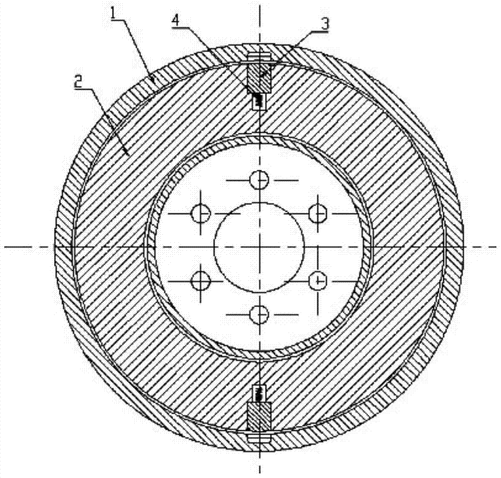
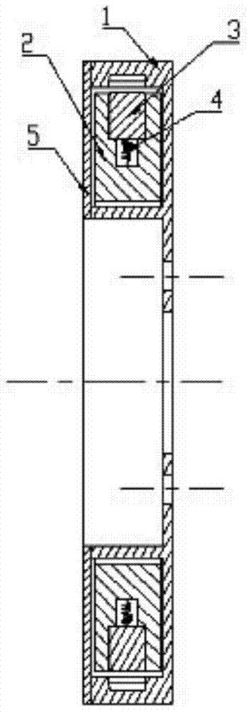
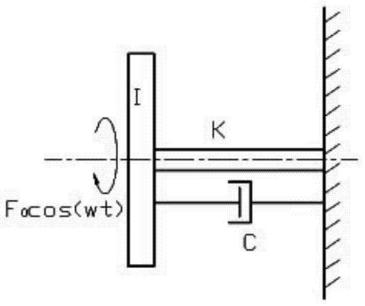
[0029] Such as Figure 1-2 As shown, the shafting frequency modulator provided by this embodiment includes a housing 1, an inertia ring 2, a positioning pin 3, an elastic member 4, and a cover plate 5. The housing 1 is installed at the front end of the crankshaft and is opened on one side of the housing 1. There is an annular mounting groove for accommodating the inertia ring 2; specifically, a mounting hole for mounting the crankshaft is provided at the center of the housing 1. The inertia ring 2 is arranged in the annular installation groove and can slide relatively along the annular installation groove; one end of the positioning pin 3 is connected to the outside of the inertia ring 2 through the elastic member 4, and the inner wall of the annular installation groove is provided with the positioning pin 3 for insertion The cover plate 5 is encapsulated above the annular mounting groove. The shafting frequency modulator can replace the shock absorber to reduce vibration, so ...
Embodiment 2
[0051] The second embodiment also provides an engine, which includes a shafting frequency modulator. The shafting frequency modulator includes a housing 1, an inertia ring 2, a positioning pin 3, an elastic component 4, and a cover plate 5. The housing 1 is installed at the front end of the crankshaft, and an annular installation groove for accommodating the inertia ring 2 is opened on one side of the housing 1 ; Specifically, the center of the housing 1 is provided with a mounting hole for mounting the crankshaft. The inertia ring 2 is set in the annular installation groove and can slide relatively along the annular installation groove; one end of the positioning pin 3 is connected to the outside of the inertia ring 2 through the elastic member 4, and the inner wall of the annular installation groove is provided with the positioning pin 3 for insertion The cover plate 5 is encapsulated above the annular mounting groove. As for other features, please refer to the first embodim...
PUM
 Abstract
Description
Claims
Application Information
 - R&D
- Intellectual Property
- Life Sciences
- Materials
- Tech Scout
- Unparalleled Data Quality
- Higher Quality Content
- 60% Fewer Hallucinations
Browse by: Latest US Patents, China's latest patents, Technical Efficacy Thesaurus, Application Domain, Technology Topic, Popular Technical Reports.
© 2025 PatSnap. All rights reserved.Legal|Privacy policy|Modern Slavery Act Transparency Statement|Sitemap|About US| Contact US: help@patsnap.com


