Eureka AIR delivers breakthrough ideas for toughest innovation challenges, trusted by R&D personnel around the world.

A new type of led flood light

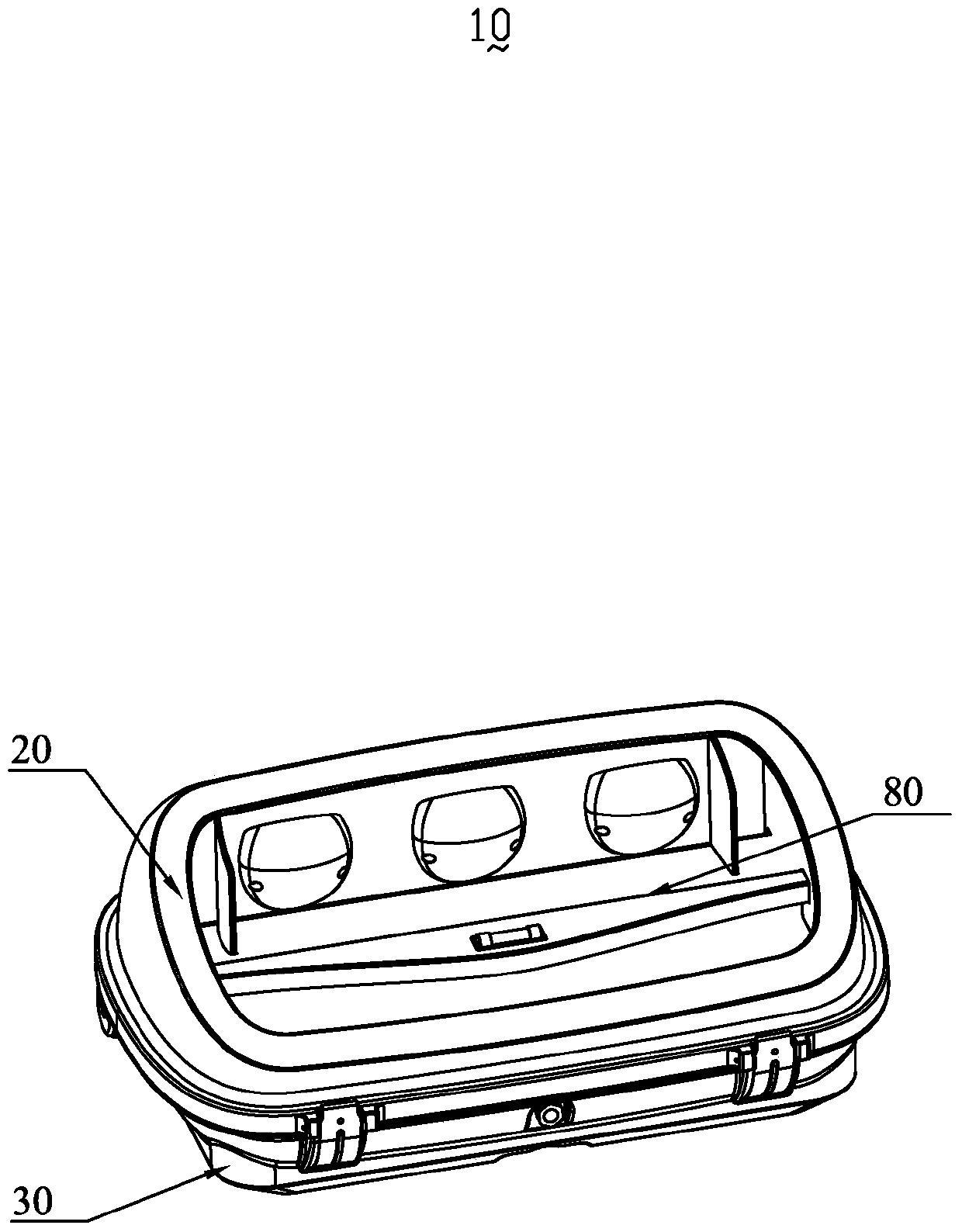
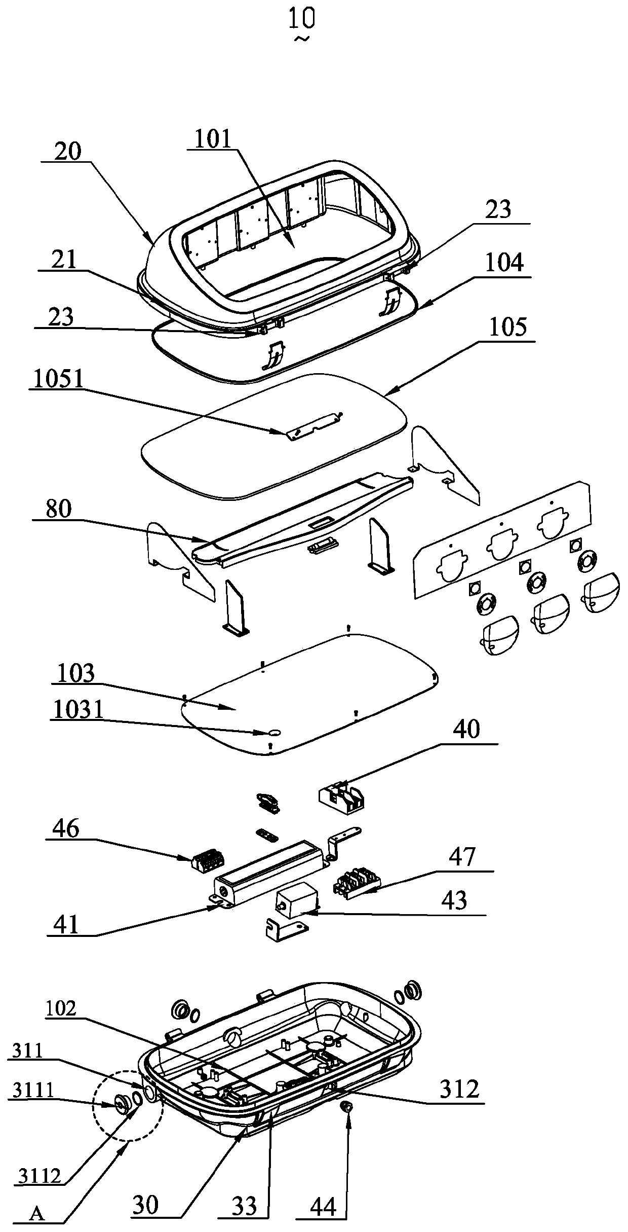
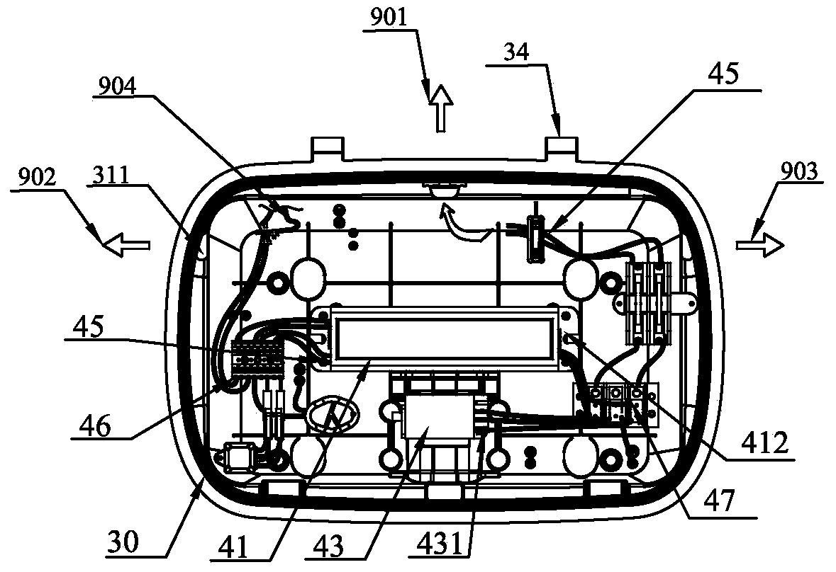
A LED floodlight, a new type of technology, applied in the direction of light source, electric light source, lighting device components, etc., can solve the problems of installation structure and light distribution structure restrictions, and achieve the effect of avoiding air circulation

Active Publication Date: 2020-05-01
SHENZHEN BANG BELL ELECTRONICS
View PDF7 Cites 0 Cited by
  • Summary
  • Abstract
  • Description
  • Claims
  • Application Information

AI Technical Summary

Problems solved by technology

[0003] Due to the limitations of the installation structure and light distribution structure, the existing LED floodlights cannot effectively meet the existing market demand. Therefore, it is urgent to provide an LED floodlight with wide practicability and high light output rate.

Method used


Image

  • A new type of led flood light
  • A new type of led flood light
  • A new type of led flood light

Examples


no. 1 Embodiment approach

[0102] see Figure 10A , the first embodiment of the light pole installation structure 90 of the LED floodlight 10 in the present invention is as follows: The light pole 96 is parallel to the second installation part 92, and the included angle between the second installation part 92 and the vertical direction is the installation angle a1. At this time, the end of the light pole 96 is in contact with the second fulcrum area 9211 of the second semi-arc surface 921, and the surface of the light pole 96 is in contact with the surface of the second mounting part 92, because the The surface of the second mounting part 92 is a continuous and smooth surface. Therefore, when the light pole 96 is in contact with the surface of the second mounting part 92 , the contact area and force bearing area can be increased. Further, two hoops 951 are used to match the nuts 952 and the screw holes 941 to fix the light pole 96 on the second shell 31 of the floodlight 10 .

no. 2 Embodiment approach

[0103] Please refer to 10B, the second embodiment of the light pole installation structure 90 of the LED floodlight described in the present invention is as follows: the difference between the second embodiment and the first embodiment is that the light pole has a cuboid shape 96 is in contact with and bonded to the first installation part 91 , and at this time, the included angle between the light pole 96 and the vertical direction is the installation angle a2. The end of the light pole 96 is in contact with the first fulcrum area 9111 of the first semi-arc surface 911, the surface of the light pole 96 is in contact with the surface of the first mounting part 91, and the surface of the light pole 96 is Only in contact with the surface of the end of the second installation part 92 away from the floodlight 10 .

[0104] Wherein, the installation angle a1 is greater than or equal to the installation angle a2, and the installation angle a1 and the installation angle a2 are more p...


PUM

PropertyMeasurementUnit
thicknessaaaaaaaaaa
lengthaaaaaaaaaa
lengthaaaaaaaaaa

Abstract

The invention provides a novel light-emitting diode (LED) projection lamp which comprises a first cavity and a second cavity. The first cavity and the second cavity are independent of each other. The LED projection lamp further comprises a light distribution structure and an electrical assembly. The light distribution structure is arranged in the first cavity. The electrical assembly is arranged in the second cavity. The LED projection lamp is beneficial to acquisition of the uniform illumination and the floodlight effect and has high light emitting efficiency.

Description

【Technical field】 [0001] The invention relates to the field of LED floodlights, in particular to a novel LED floodlight. 【Background technique】 [0002] LED (Light-Emittng Diode) is a type of light-emitting device that can directly convert electrical energy into visible light and radiant energy. It has the advantages of high efficiency, low power consumption, long life, high luminous quality, and pure light color. Among them, LED floodlights have higher requirements for the angle of the outgoing beam and the brightness of the lighting due to the lighting of road advertisements, large-scale operation sites, mines, building outlines, parks and flower beds. [0003] Due to the limitations of the installation structure and light distribution structure, the existing LED floodlights cannot effectively meet the existing market demand. Therefore, it is urgent to provide an LED floodlight with wide practicability and high light output rate. 【Content of invention】 [0004] In order...

Claims


Application Information

Patent Timeline
Patent Type & Authority Patents(China)
IPC IPC(8): F21S8/00F21V7/00F21V5/04F21V23/06F21V25/12F21V31/00F21Y115/10
CPCF21S8/00F21V5/04F21V7/00F21V23/06F21V25/12F21V31/00
Inventor 何琳李盛远李剑
Owner SHENZHEN BANG BELL ELECTRONICS
Why Eureka
Eureka Blog
Learn More