Optical sensor, modulator and manufacturing method based on slab waveguide resonant coupling

A resonant coupling, planar waveguide technology, applied in the direction of converting sensor output, using optical devices to transmit sensing components, instruments, etc., can solve the problems of increasing process complexity, reducing polarization correlation, and wet grinding and polishing process environment. The effect of flexible control of groove shape and width, increased possibility of shape and position, and simplified film thickness control process

Active Publication Date: 2018-05-22
CENT SOUTH UNIV
View PDF5 Cites 0 Cited by
  • Summary
  • Abstract
  • Description
  • Claims
  • Application Information

AI Technical Summary

Problems solved by technology

[0006] The traditional side grinding and polishing method has the following defects: On the one hand, before the traditional grinding and polishing process is produced, it generally requires a tool to scratch a groove on the quartz block, and the optical fiber is embedded and glued in the groove; the grinding process requires output of the optical fiber. The change of optical power is monitored in real time to determine the thickness of the remaining fiber core. The light source and optical power meter must be connected during the entire grinding process, which increases the complexity of the manufacturing process; and the traditional grinding and polishing process has a humid environment and has special requirements for solvents.
On the other hand, when the traditional grinding and polishing process is used to make the side grinding and polishing fiber, the side must be completely ground and polished. When the coated side of the ground and polished side is thin, the refractive index of the external environment needs to be close to the fiber material, so that the TE , The polarization dependence of the TM mode is small; in order to make up for this defect, many researchers adopt the method of increasing the film thickness, that is, the cover film adopts a thick film to reduce the polarization dependence, but the free spectral range of the sensor is reduced. thus limiting the application range of the device
In addition, the film thickness control process of the cover film in the traditional production process is harsh and complicated. These factors make it difficult to practically use side grinding and polishing optical fibers.

Method used


Image

  • Optical sensor, modulator and manufacturing method based on slab waveguide resonant coupling
  • Optical sensor, modulator and manufacturing method based on slab waveguide resonant coupling
  • Optical sensor, modulator and manufacturing method based on slab waveguide resonant coupling

Examples


Embodiment Construction

[0041] The following will clearly and completely describe the technical solutions in the embodiments of the present invention with reference to the accompanying drawings in the embodiments of the present invention. Obviously, the described embodiments are only some, not all, embodiments of the present invention. Based on the embodiments of the present invention, all other embodiments obtained by persons of ordinary skill in the art without making creative efforts belong to the protection scope of the present invention.

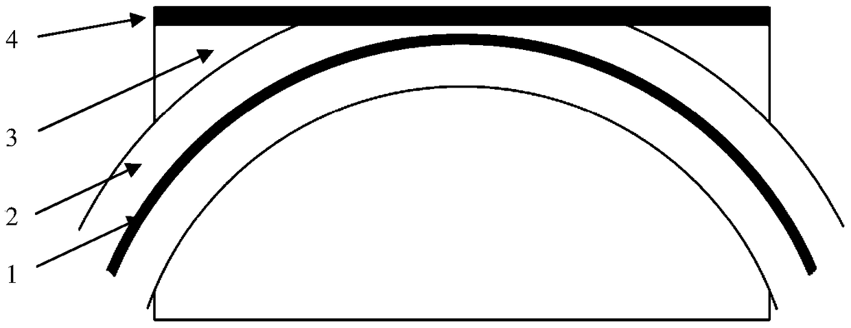
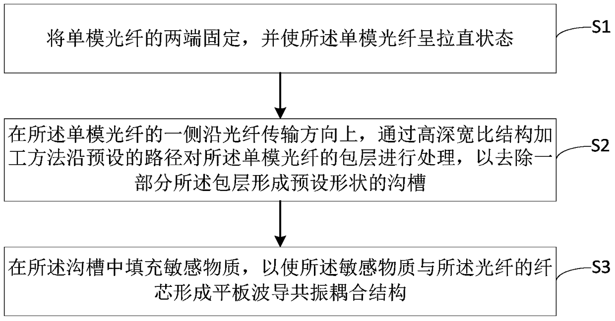
[0042] figure 2 It shows a schematic flow chart of a method for manufacturing an optical sensor based on slab waveguide resonant coupling provided by an embodiment of the present invention, and the method includes the following steps:

[0043] S1: fixing both ends of the single-mode fiber, and making the single-mode fiber straighten.

[0044] Specifically, in this step, the single-mode optical fiber can be fixed on a special fixture, and the single-mode opti...


PUM


Abstract

The invention provides an optical sensor based on planar waveguide resonance coupling, a modulator and a manufacturing method thereof. Specifically, the optical sensor comprises an optical fiber sensor and an optical waveguide type sensor. The optical modulator comprises an optical fiber modulator and an optical waveguide type modulator. The method comprises the steps that the two ends of a single-mode optical fiber are fixed, and the single-mode optical fiber is enabled to be in the straightened state; the cladding of the single-mode optical fiber is processed by a high depth-to-width ratio structure processing method along a preset path at one side of the single-mode optical fiber along the optical fiber transmission direction so as to remove a part of the cladding and form a groove of the preset shape; and sensitive material is filled in the groove so that a planar waveguide resonance coupling structure is formed by the sensitive substance and the fiber core of the optical fiber. Long time of online monitoring can be avoided, the film thickness control technology can be simplified, groove shape and width control is flexible, and the optical fiber sensor and the modulator are simple and compact in structure and high in sensitivity.

Description

technical field [0001] The invention relates to the technical field of preparation of optical fibers and optical waveguide devices, in particular to an optical sensor, a modulator and a manufacturing method based on slab waveguide resonance coupling. Background technique [0002] Side-polished optical fiber is an optical fiber made by polishing off a part of the cylindrical optical fiber cladding on a certain length of the optical fiber by using optical micro-processing technology on the ordinary communication optical fiber. The section of the cladding polished The cross-section of the fiber is similar to the capital letter D, and in the unpolished fiber section, it is still cylindrical. [0003] Usually, a sufficiently thick fiber cladding ensures that the optical field propagating in the fiber core and the energy of the evanescent wave field in the fiber cladding will not leak out of the fiber. When the cladding thickness of the optical fiber is reduced to the area where ...

Claims


Application Information

Patent Timeline
Patent Type & Authority Patents(China)
IPC IPC(8): G01D5/26
CPCG01D5/268
Inventor 周剑英段吉安孙小燕郑煜王聪王华
Owner CENT SOUTH UNIV
Why Eureka
Try Eureka