
Device for measuring Seebeck coefficient and method of device

A measurement method and coefficient technology, applied in the direction of measuring device, measuring heat, using electric device, etc., can solve the problems of high measurement accuracy of Seebeck coefficient and high requirements for measuring sample shape, so as to improve temperature measurement accuracy, improve measurement accuracy, The effect of overcoming shape constraints

Inactive Publication Date: 2016-06-01
HUAZHONG UNIV OF SCI & TECH
View PDF7 Cites 15 Cited by
  • Summary
  • Abstract
  • Description
  • Claims
  • Application Information

AI Technical Summary

Problems solved by technology

[0006] For the above defects or improvement needs of the prior art, the object of the present invention is to provide a device and method for measuring the Seebeck coefficient, wherein by improving the key measurement principle of the device, the structure of each component and its setting method, etc., Compared with the existing technology, it can effectively solve the problem of high requirements for measuring the shape of the sample. The shape of the sample to be measured can be flexible and diverse, and the device can test the Seebeck coefficient of the material under different temperature conditions. The structure of the device is simple. Based on the test method of obtaining multiple sets of Seebeck coefficients by four probes and then averaging, the measured Seebeck coefficients have high measurement accuracy

Method used


Image

  • Device for measuring Seebeck coefficient and method of device
  • Device for measuring Seebeck coefficient and method of device
  • Device for measuring Seebeck coefficient and method of device

Examples


Embodiment 1

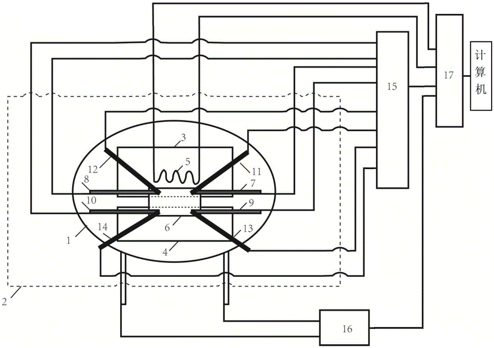
[0051] Such as figure 1 As shown, the device for measuring the Seebeck coefficient includes a main heater 1, an auxiliary heater 5, a first insulating heat conductor 3, a second insulating heat conductor 4, a first main probe 11, a first auxiliary probe 12, a second main probe Probe 13, second auxiliary probe 14, first main thermocouple 7, first auxiliary thermocouple 8, second main thermocouple 9 and second auxiliary thermocouple 10; wherein,

[0052] The first insulated heat conductor 3 and the second insulated heat conductor 4 are all located on the main heater 1, and the first insulated heat conductor 3 and the second insulated heat conductor 4 are not in direct contact; the first insulated heat conductor 3 and the second insulated heat conductor The thermal conductors 4 are all used to place the sample to be measured; one end of the sample to be measured is in contact with the first insulating thermal conductor 3, and the other end is in contact with the second insulating...


PUM


Abstract

The invention discloses a device for measuring a Seebeck coefficient and a method of the device. The device comprises a main heater, an assistant heater, a first insulated thermal conductor, a second insulated thermal conductor, a first main probe, a first assistant probe, a second main probe, a second assistant probe, a first main thermocouple, a first assistant thermocouple, a second main thermocouple and a second assistant thermocouple; the first insulated thermal conductor and the second insulated thermal conductor are both used for carrying a sample to be measured; the first main probe, the first assistant probe, the second main probe and the second assistant probe are used for measuring the electric potential of the sample to be measured; the first main thermocouple, the first assistant thermocouple, the second main thermocouple and the second assistant thermocouple are used for measuring the temperature of the sample to be measured. The morphology of the measured sample can be flexible and diverse, the device can measure the material Seebeck coefficients under the different temperature conditions and is simple in structure, and due to the fact that the measurement method that an average value is resolved through multiple sets of the Seebeck coefficients which are resolved on the basis of the four probes is adopted, the measured Seebeck coefficient is high in measurement accuracy.

Description

technical field [0001] The invention belongs to the technical field of test devices, and more particularly relates to a device and method for measuring Seebeck coefficients. Background technique [0002] Recently, thermoelectric materials, an emerging energy conversion material, have attracted more and more attention. It is a functional material that realizes mutual conversion of thermal energy and electrical energy through carrier transport in semiconductor materials. Thermoelectric materials have a series of advantages such as no noise during operation, no need for transmission parts, cleanliness, environmental protection, and long service life, making this material have a wide and bright application prospect. This makes it particularly important to test the performance of thermoelectric materials, and the Seebeck coefficient is one of the important performance parameters of thermoelectric materials. The Seebeck coefficient, also known as the Seebeck coefficient, is an in...

Claims


Application Information

Patent Timeline
Patent Type & Authority Applications(China)
IPC IPC(8): G01N25/20G01R19/00G01K7/02
CPCG01K7/02G01N25/20G01R19/0084
Inventor 杨君友何煦罗裕波张旦周志伟瞿秋亮姜庆辉任洋洋
Owner HUAZHONG UNIV OF SCI & TECH
Learn More