Indoor supersonic wave positioning position correction method

A technology of positioning position and ultrasonic wave, applied in the field of navigation

Inactive Publication Date: 2016-06-01
NANCHANG UNIV
View PDF5 Cites 9 Cited by
  • Summary
  • Abstract
  • Description
  • Claims
  • Application Information

AI Technical Summary

Problems solved by technology

[0008] Aiming at the defects existing in the existing ultrasonic indoor positioning method,

Method used


Image

  • Indoor supersonic wave positioning position correction method
  • Indoor supersonic wave positioning position correction method
  • Indoor supersonic wave positioning position correction method

Examples


Embodiment Construction

[0034] In order to realize high-precision indoor ultrasonic three-dimensional positioning, the present invention provides an indoor ultrasonic positioning position correction method. Below in conjunction with accompanying drawing, the technical scheme of invention is described in detail:

[0035] The system structure of the indoor ultrasonic positioning system:

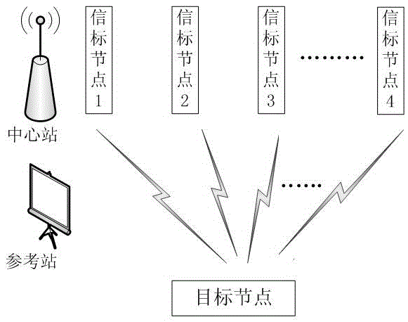
[0036] Such as figure 1 The structural composition diagram of the indoor ultrasonic positioning system is mainly composed of four parts: the central station, the beacon node, the target node and the reference station. The specific positioning steps of the four parts are as follows:

[0037] Let the coordinates of the three beacon nodes deployed at fixed positions on the roof be (x 1 ,y 1 ,z 1 ), (x 2 ,y 2 ,z 2 ), (x 3 ,y 3 ,z 3 ); set the position coordinates of the reference station as (x u ,y u ,z u ), the subscript u is the label of the reference station;

[0038] (1) The central station transmits a ...


PUM


Abstract

The invention discloses an indoor supersonic wave positioning position correction method. A positioning system consists of a center station, a beacon node, an object node and a reference station. The indoor supersonic wave positioning position correction method can eliminate the positioning errors caused by a supersonic wave speed error, a hardware delay error, an installation error and other errors. Compared with the prior art, the position information accuracy of the object node obtained through the indoor supersonic wave positioning position correction method is high.

Description

technical field [0001] The invention relates to an indoor ultrasonic positioning position correction method; the position correction method is used to perform error compensation to improve indoor positioning accuracy, and is used for precise positioning of indoor objects, belonging to the technical field of navigation. Background technique [0002] Indoor positioning technology has become a research hotspot in recent years. With the continuous development of indoor positioning technology, people's lives will become more and more convenient. [0003] Ultrasonic indoor positioning technology has the characteristics of low cost, strong anti-electromagnetic interference ability, unaffected by light and smoke, intuitive time information and high positioning accuracy. Therefore, ultrasonic positioning technology is widely used in various ranging and positioning systems. [0004] Commonly used ultrasonic-based indoor positioning technologies mainly include: [0005] The first is ...

Claims


Application Information

Patent Timeline
IPC IPC(8): G01S5/18
CPCG01S5/18
Inventor 熊剑周先赞杨祖华杨欢郭杭林舟杰马号徐江颖
Owner NANCHANG UNIV
Why Eureka
Try Eureka