Coupling lens device applied to vertical cavity surface emitting laser

A technology of vertical cavity surface emission and coupling lens, applied in the field of coupling lens, can solve problems such as inability to sense and monitor, communication system failure, non-luminous luminous efficiency, etc.

Inactive Publication Date:
View PDF5 Cites 9 Cited by
  • Summary
  • Abstract
  • Description
  • Claims
  • Application Information

AI Technical Summary

Problems solved by technology

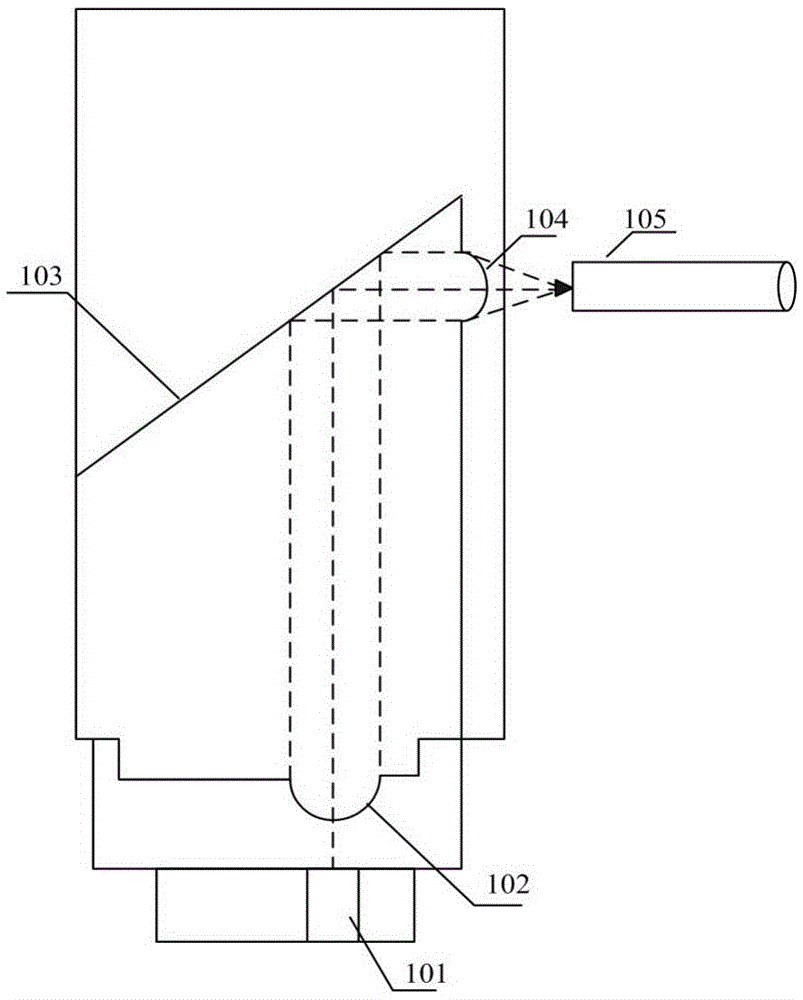
However, if the VCSEL laser at position 101 does not emit light or the luminous efficiency decreases due to emission failure, this board cannot sense and monitor
Once the VCSEL laser fails due to emission, the entire communication system will fail. Since the working status of the VCSEL is not monitored, communication system managers cannot quickly and conveniently locate the fault point

Method used


Image

  • Coupling lens device applied to vertical cavity surface emitting laser
  • Coupling lens device applied to vertical cavity surface emitting laser
  • Coupling lens device applied to vertical cavity surface emitting laser

Examples


Embodiment Construction

[0035] The present invention will be further described in detail below in conjunction with the accompanying drawings, so that those skilled in the art can implement it with reference to the description.

[0036] It should be understood that terms such as "having", "comprising" and "including" as used herein do not entail the presence or addition of one or more other elements or combinations thereof.

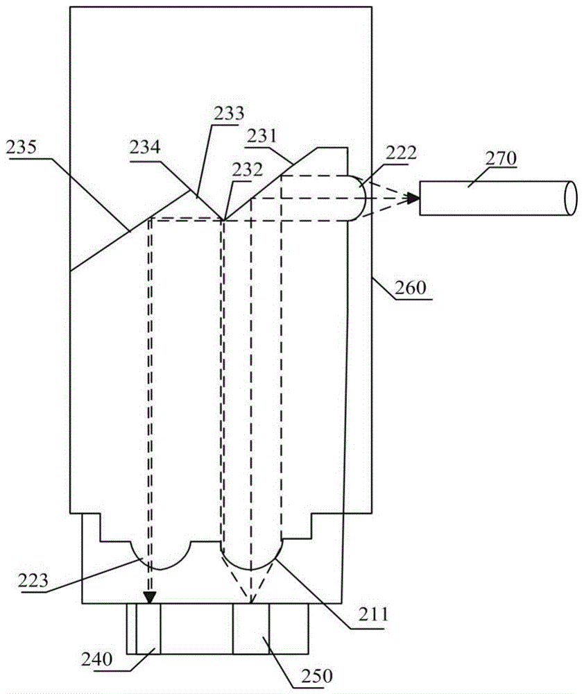
[0037] like Figure 2-3 Shown is an implementation form of a coupling lens device applied to a vertical cavity surface emitting laser according to the present invention, which includes:

[0038] light incident unit 210;

[0039] Light emitting unit 220;

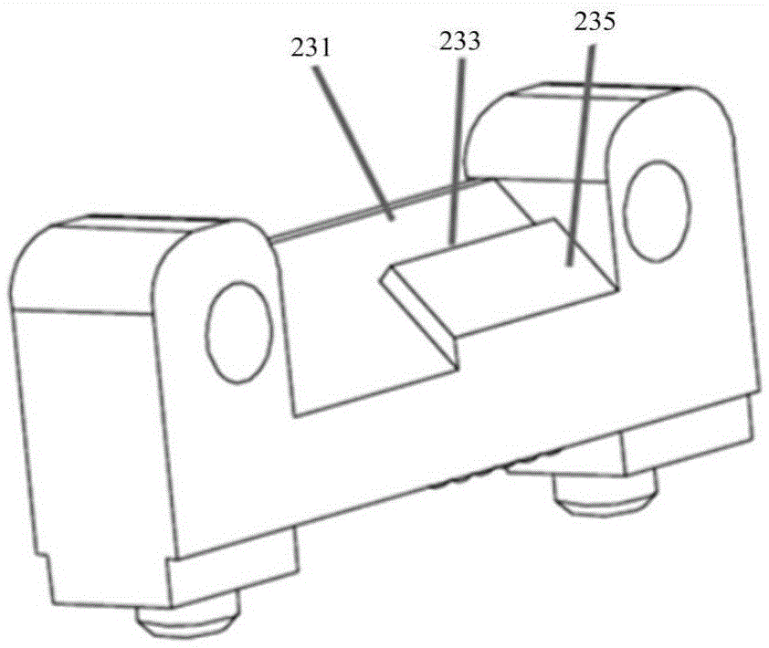
[0040] The light reflection unit 230 arranged between the light path of the light incident unit and the light exit unit includes a first light reflection mechanism 231 and a first corner 232 having a preset angle with the first light reflection mechanism, and the light exits a second light reflection mechanism 233 with disjoi...


PUM


Abstract

The invention discloses a coupling lens device applied to a vertical cavity surface emitting laser. The coupling lens device comprises a light inlet unit, a light outlet unit and a light reflection unit, wherein the light reflection unit is arranged between light paths of the light inlet unit and the light outlet unit and comprises a first light reflection mechanism, a first corner and a second light reflection mechanism; a first preset angle is formed between the first light reflection mechanism and the first corner; and the light outlet directions of the first light reflection mechanism and the second light reflection mechanism are not intersected. According to the coupling lens device applied to the vertical cavity surface emitting laser, laser beams emitted by a VCSEL can be coupled into an optical fiber, a small part of laser beams can be split to return to a board, optical signals of the beams can be converted into electric signals by virtue of a backlight diode placed on the board, and thus the light emitting state of the VCSEL can be obtained by virtue of a subsequent signal processing circuit.

Description

technical field [0001] The invention relates to a coupling lens used in an optical transceiver. More particularly, the present invention relates to a coupling lens arrangement for use in a vertical cavity surface emitting laser. Background technique [0002] The explosive growth of Internet technologies such as big data and cloud computing has promoted the rapid development of optical interconnection and communication products. Vertical cavity surface emitting lasers (hereinafter referred to as VCSELs) have become the most suitable for short-distance optical interconnection due to their low cost and easy coupling. good choice. With the improvement of communication speed and port density of communication equipment, the use of arrayed VCSEL lasers has become a technical trend, and the traditional coaxial-based packaging technology is no longer suitable for arrayed VCSEL lasers. At present, the mainstream method is to mount most of the array lasers directly on the printed cir...

Claims


Application Information

Patent Timeline
Patent Type & Authority Applications(China)
IPC IPC(8): G02B6/42
CPCG02B6/4204G02B6/4214G02B6/4286G02B6/4296
Inventor 范巍陈气超
Why Eureka
Try Eureka