Near-to-eye display optical system
A near-eye display and optical system technology, applied in optics, optical components, instruments, etc., can solve the problems of uneven color and brightness of virtual images, and achieve the effects of reducing discomfort, low dispersion, and ensuring uniformity
- Summary
- Abstract
- Description
- Claims
- Application Information
AI Technical Summary
Problems solved by technology
Method used
Image
Examples
Embodiment 1
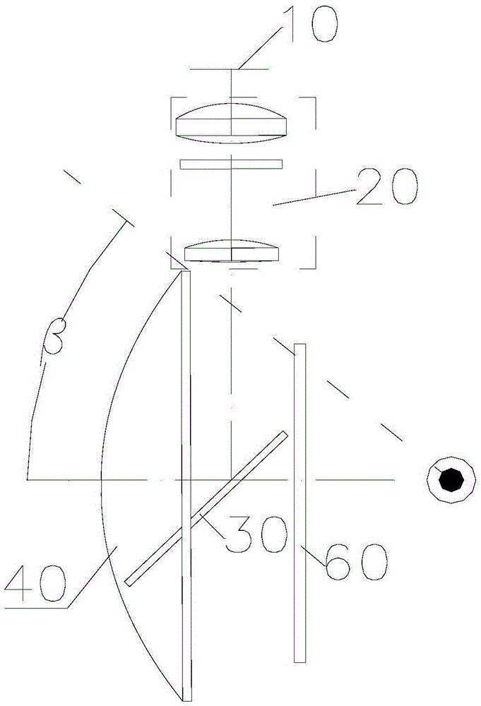
[0033] Please refer to figure 2 , figure 2 A schematic diagram of the optical path of the near-eye display optical system provided in Embodiment 1 of the present invention, as shown in figure 2 As shown, the near-eye display optical system includes an image source 10, a relay imaging mirror group 20, a reversible and lensable flat mirror 30 and a reversible and transparent concave mirror 40;
[0034] like figure 2 As shown, the image light output by the image source 10 is reflected by the reflective and transparent flat mirror 30 to the reflective and transparent concave mirror 40 after passing through the relay imaging mirror group 20, after being enlarged and reflected by the reflective and transparent concave mirror 40, and then passed through After being transmitted by the reflective and transparent flat mirror 30, it is received by the human eyes, and the image light here is a virtual image for the human eyes; the external ambient light is transmitted by the reflect...
Embodiment 2
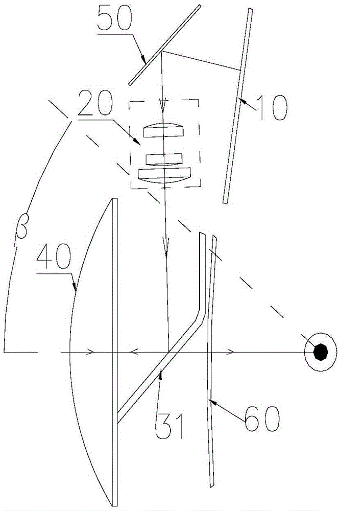
[0051] Please refer to image 3 , image 3 A schematic diagram of the optical path of the near-eye display optical system provided in Embodiment 2 of the present invention, as shown in image 3 As shown, the near-eye display optical system includes an image source 10 , a relay imaging lens group 20 , a reflective and transparent plane mirror 31 , a reflective and transparent concave mirror 40 and a plane total reflection mirror 50 .
[0052] Please continue to refer image 3 , in this embodiment, the image source 10 is specifically a 5.0-inch display screen, which is arranged on the side of the relay imaging mirror group 20 close to the forehead of the person, and a plane total reflection mirror 50 is arranged above the relay imaging mirror group 20, which can The reflective mirror 31 is disposed below the relay imaging lens group 20 , and the reflective mirror 31 is located between the reflective concave mirror 40 and the human eye.
[0053] like image 3 As shown, after ...
Embodiment 3
[0065] Please refer to Figure 5 , Figure 5 A schematic diagram of the optical path of the near-eye display optical system provided in Embodiment 3 of the present invention, as shown in Figure 5 As shown, the near-eye display optical system provided by this embodiment includes an image source 10 , a relay imaging lens group 20 , a reflective and transparent flat mirror 30 , a reflective and transparent concave mirror 40 and a flat total reflection mirror 51 .
[0066] like Figure 5 As shown, the image light output by the image source 10 is reflected by the plane total reflection mirror 51 to the reversible and transparent plane mirror 30 after passing through the relay imaging mirror group 20, and then reflected by the reversible and transparent plane mirror 30 to the reversible and permeable concave mirror 40, after being magnified and reflected by the reversible and permeable concave mirror 40, it is transmitted by the reversible and permeable plane mirror 30 and then r...
PUM
 Abstract
Description
Claims
Application Information
 - R&D
- Intellectual Property
- Life Sciences
- Materials
- Tech Scout
- Unparalleled Data Quality
- Higher Quality Content
- 60% Fewer Hallucinations
Browse by: Latest US Patents, China's latest patents, Technical Efficacy Thesaurus, Application Domain, Technology Topic, Popular Technical Reports.
© 2025 PatSnap. All rights reserved.Legal|Privacy policy|Modern Slavery Act Transparency Statement|Sitemap|About US| Contact US: help@patsnap.com


