
Array substrate and manufacturing method therefor, and display apparatus

An array substrate and display area technology, applied in semiconductor/solid-state device manufacturing, instrumentation, semiconductor/solid-state device testing/measurement, etc., can solve the problems of increased space occupied by test components, scattered distribution of test components, and reduced test efficiency, etc. Achieve the effect of improving timeliness, saving space, and reducing process testing costs

Active Publication Date: 2016-06-01
BOE TECH GRP CO LTD
View PDF4 Cites 7 Cited by
  • Summary
  • Abstract
  • Description
  • Claims
  • Application Information

AI Technical Summary

Problems solved by technology

[0005] The existing test unit is to design multiple test elements on different layers in the non-display area. Among these test elements, they are used to test the line width of the signal line, the overlap between the upper and lower conductive film layers, and the long channel and short channel. The test elements of the transistor characteristics of the channel are set independently, and the distribution of the test elements in the non-display area is scattered, which not only increases the occupied space of the test elements in the non-display area, which is not conducive to saving the preparation cost, but also in the When testing different process parameters, it is necessary to frequently move the test equipment (such as optical test equipment and electrical test equipment), which greatly reduces the test efficiency and increases the test cost

Method used


Image

  • Array substrate and manufacturing method therefor, and display apparatus
  • Array substrate and manufacturing method therefor, and display apparatus
  • Array substrate and manufacturing method therefor, and display apparatus

Examples


Embodiment 1

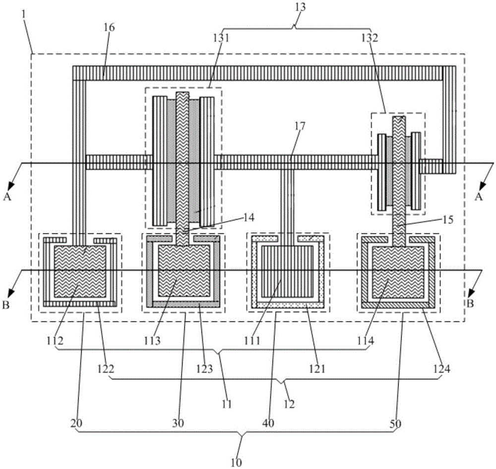
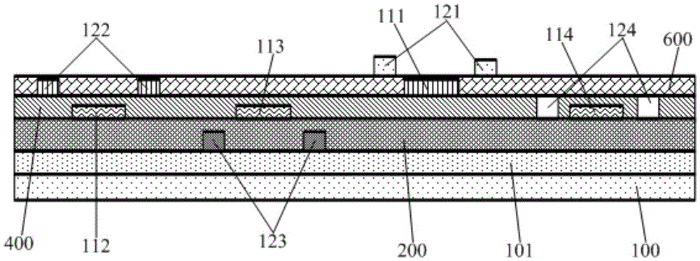
[0053] This embodiment provides an array substrate, such as figure 1 and figure 2 As shown, it includes a multi-layer pattern layer arranged in the display area and a test unit 1 arranged in a non-display area. The test unit 1 includes at least one test assembly 10 and a test transistor 13. The test assembly 10 includes a test block pattern 11 and a test line. Graphic 12; test block graphics 11 and one layer of the multi-layer pattern layer are arranged on the same layer, and one layer of the test line pattern 12 is set on the same layer as the multi-layer pattern layer, and the test block pattern 11 and the test line pattern 12 are different layers, The orthographic projection of the test line pattern 12 on the array substrate corresponds to the periphery of the orthographic projection of the test block pattern 11 on the array substrate; the test block pattern 11 is connected to the test transistor 13 .

[0054] In this embodiment, the orthographic projection of the test li...

Embodiment 2

[0086] This embodiment provides an array substrate. The difference from Embodiment 1 is that the test unit in this embodiment only includes one test component, and the test component can be the first test component, the second test component, the second test component, The third test component or the fourth test component; it can also be other test components similar to the first test component, the second test component, the third test component or the fourth test component in the arrangement.

[0087] In this embodiment, the test unit may or may not include a test transistor. The gate, source and drain of the test transistor can be connected to different test block patterns or test line patterns respectively, and the test signal is sent from the test block pattern or test line pattern; they can also not be connected to the test block pattern or test line pattern , directly sent to the test signal by the external test equipment.

[0088] It should be noted that the test unit i...

Embodiment 3

[0092] This embodiment provides a display device, including the array substrate in Embodiment 1 or 2.

[0093] By adopting the array substrate in Embodiment 1 or 2, not only the cost of the process capability test of the display device is reduced, but also the timeliness of the process capability test of the display device is improved.

[0094] The display device may be any product or component with a display function such as a mobile phone, a tablet computer, a television, a monitor, a notebook computer, a digital photo frame, a navigator, and the like.


PUM


Abstract

The invention provides an array substrate and a manufacturing method therefor, and a display apparatus. The array substrate comprises multiple pattern layers in a display region and a test unit in a non-display unit, wherein the test unit comprises at least onetest assembly and test transistors; the test assemblies comprise test block patterns and test line patterns; the test block patterns and one layer of the multiple pattern layers are arranged on the same layer; the test line patterns and one layer of the multiple pattern layers are arranged on the same layer, and the test block patterns and the test line patterns are positioned on different layers; the periphery of the orthographic projection of the test block patterns is surrounded by the orthographic projection of the test line patterns on the array substrate; and the test block patterns or the test line patterns are connected with the test transistors. According to the array substrate, the integration testing for the pattern dimensions of the multiple pattern layers and the mutual overlaying degrees of the multiple pattern layers in the display region can be realized; and the integration testing on the characteristics of the transistors in the display region can be realized as well, so that the technology test cost is lowered and the technology test timeliness is improved.

Description

technical field [0001] The present invention relates to the field of display technology, in particular, to an array substrate, a manufacturing method thereof, and a display device. Background technique [0002] As people's demand for high-resolution displays is getting higher and higher, high-resolution display products have higher and higher requirements for process capabilities. Therefore, the timeliness requirements for process capability testing during the display manufacturing process are also relatively increased. [0003] Especially for polysilicon display devices with a top-gate structure, due to the large number of exposures in the manufacturing process of the display device, the process is relatively complicated. If the process cannot be immediately reflected in the production process, the product will be damaged. The production cost and time are greatly wasted, which requires monitoring the stability and accuracy of the process during or after the process. [000...

Claims


Application Information

Patent Timeline
Patent Type & Authority Applications(China)
IPC IPC(8): H01L21/66H01L27/12H01L21/77
CPCH01L22/34H01L27/1222H01L27/127H01L27/124G02F1/1309H01L27/1214G02F1/136254H01L21/77H01L27/12G02F1/134363G02F1/136286G02F1/1368
Inventor 詹裕程张帅
Owner BOE TECH GRP CO LTD
Learn More