Overhead power transmission line laying device

A technology of transmission lines and transmission devices, applied in the direction of overhead lines/cable equipment, etc., can solve the problems of personal and equipment injury accidents, the inability to accurately and effectively ensure the accuracy and self-heavyness of power cables, and reduce construction risks and labor intensity , Improve erection efficiency and erection quality, good sag and tension effect

Active Publication Date: 2016-06-01
STATE GRID CORP OF CHINA +1
View PDF5 Cites 8 Cited by
  • Summary
  • Abstract
  • Description
  • Claims
  • Application Information

AI Technical Summary

Problems solved by technology

[0002] With the requirement of long-distance power transmission, a large number of high-voltage transmission lines need to be suspended and erected through power poles and towers. Due to the lack of professional construction equipment, in traditional construction, it is often necessary to use large-scale hoisting engineering machinery, or rely on construction personnel to manually lift it, resulting in high construction costs and low construction efficiency in traditional construction. In addition, personal and equipment injury accidents occur. At the same time, due to the heavy weight of the power cable, after it is suspended in the air, it will cause serious sagging due to its own weight, resulting in the distance between the power cable and the ground being less than the national safety regulations. At present, there is no professional response equipment in construction, and construction still needs to be carried out by manpower or large-scale construction machinery or vehicles. As a result, on the one hand, the construction cost is high, the construction efficiency is low, and personal and equipment injury accidents occur. It is also impossible to accurately and effectively ensure the accuracy of the power cable when adjusting the sagging height, resulting in poor construction quality and threatening the safety of electricity use

Method used


Image

  • Overhead power transmission line laying device
  • Overhead power transmission line laying device

Examples


Embodiment Construction

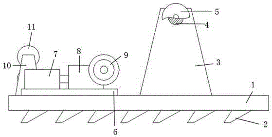
[0012] Such as figure 1 The above-mentioned upper-line device for a suspended transmission line is composed of a pay-off table and an upper wire frame, and there are at least two upper wire frames. Evenly distributed wedge-shaped anti-skid groove 2, the upper surface is respectively connected with the hinge frame, the guide wheel group and the driving mechanism, wherein the hinge frame is composed of a column 3 and a beam 4, and the column 3 is perpendicular to the base 1 and the beam 4 respectively, and the end of the beam 4 is separately provided Block 5, drive mechanism is made of positioning plate 6, drive motor 7, transmission 8 and drive wheel 9, drive motor 7, transmission 8 and drive wheel 9 are all installed on the positioning plate 6, and drive motor 7 passes through transmission 8 are respectively connected with the driving wheel 9 and the lead wheel group, the positioning plate 6 is connected with the base 1 through bolts, the lead wheel group is composed of a fram...


PUM


Abstract

The invention discloses an overhead power transmission line laying device composed of a line laying table and a line laying frame. The line laying table is formed by a pedestal, a strand frame, a wire wheel group, and a driving mechanism. The upper surface of the pedestal is connected with the strand frame, the wire wheel group, and the driving mechanism. The driving mechanism is formed by a positioning board, a driving motor, a transmission device, and a driving wheel. The driving motor, the transmission device, and the driving wheel are all installed on the positioning board. The wire wheel group is composed of a frame and at least two wire-pressing wheels installed on the frame and distributed oppositely. The line laying frame is composed of a frame body, a positioning clamp, a line laying clamp, a hauling cable, a guiding wheel, a rope strand wheel, and a driving device. The frame body is a rectangular structure formed by sidewalls and a base plate. The overhead power transmission line laying device may hoist heavy cables, such as power cables, steel strand wires and the like from ground to an assigned height of a power transmission pole, may extend the laid cables, and assures the laid power cables of good sag degrees and tension force.

Description

technical field [0001] The invention relates to an online device for a suspended transmission line, which belongs to the field of transmission line erection tools and equipment. Background technique [0002] With the requirement of long-distance power transmission, a large number of high-voltage transmission lines need to be suspended and erected through power poles and towers. Due to the lack of professional construction equipment, in traditional construction, it is often necessary to use large-scale hoisting engineering machinery, or rely on construction personnel to manually lift it, resulting in high construction costs and low construction efficiency in traditional construction. In addition, personal and equipment injury accidents occur. At the same time, due to the heavy weight of the power cable, after it is suspended in the air, it will cause serious sagging due to its own weight, resulting in the distance between the power cable and the ground being less than the nat...

Claims


Application Information

Patent Timeline
Patent Type & Authority Applications(China)
IPC IPC(8): H02G1/04
Inventor 王小趁王卫军
Owner STATE GRID CORP OF CHINA
Why Eureka
Try Eureka