Motor rotor winding method

A winding method and technology for motor rotors, which are used in the manufacture of motor generators, electrical components, electromechanical devices, etc., can solve the problems of uneven resistance of motor rotor windings, increased stall torque deviation, and increased motor power consumption. Achieve the effects of less energy loss, small stall torque deviation, and extended service life

Active Publication Date: 2016-06-01
HAIAN LIANKE AUTOMOBILE PARTS
View PDF4 Cites 6 Cited by
  • Summary
  • Abstract
  • Description
  • Claims
  • Application Information

AI Technical Summary

Problems solved by technology

[0003] The micro motor is the heart of the automotive window regulator. At present, the increase of the stall torque deviation of the motor leads to the increase of the power consumption of the motor and the shortening of the life of the motor. This problem has always existed in the manufacture and use of the motor. The reason is still due to the resistance of the motor rotor winding. caused by uneven

Method used


Image

  • Motor rotor winding method
  • Motor rotor winding method

Examples


Embodiment Construction

[0018] The application will be further described in detail below in conjunction with the accompanying drawings and embodiments. It should be understood that the specific embodiments described here are only used to explain related inventions, rather than to limit the invention. It should also be noted that, for ease of description, only parts related to the invention are shown in the drawings.

[0019] It should be noted that, in the case of no conflict, the embodiments in the present application and the features in the embodiments can be combined with each other. The present application will be described in detail below with reference to the accompanying drawings and embodiments.

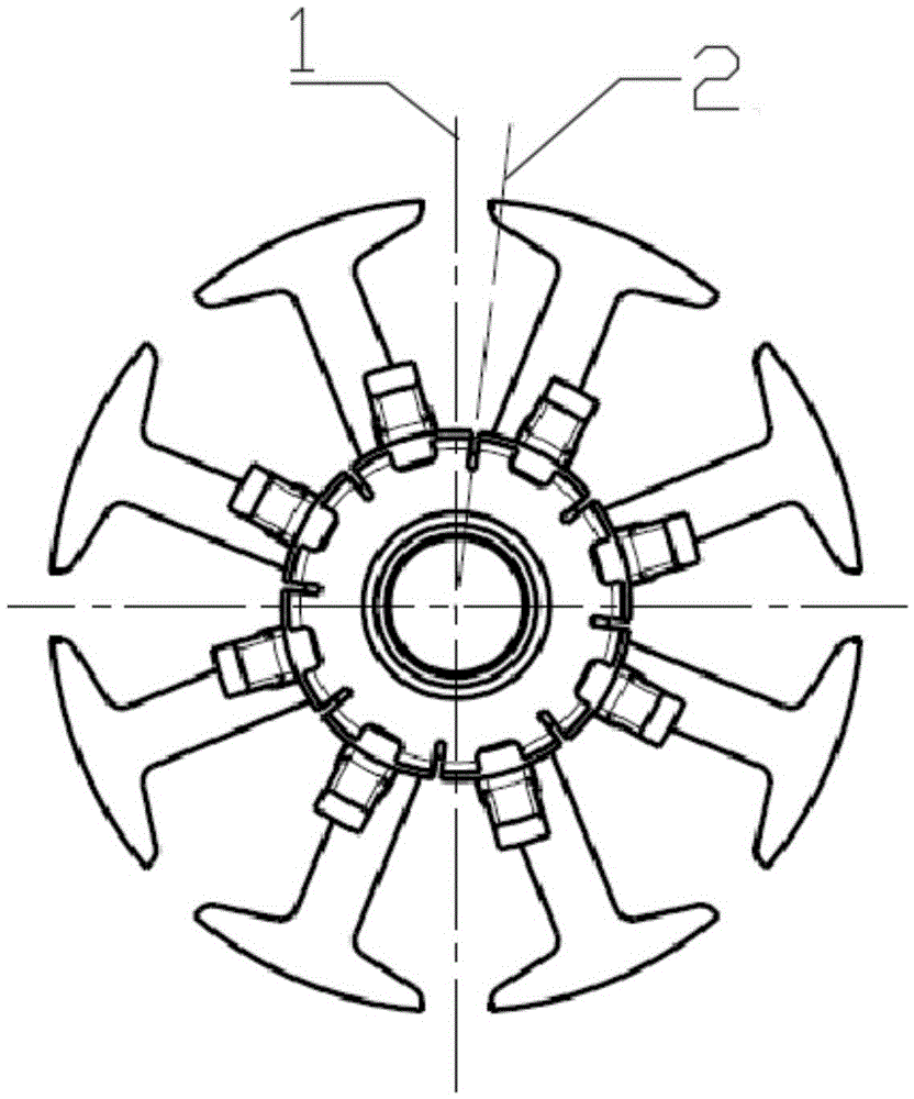
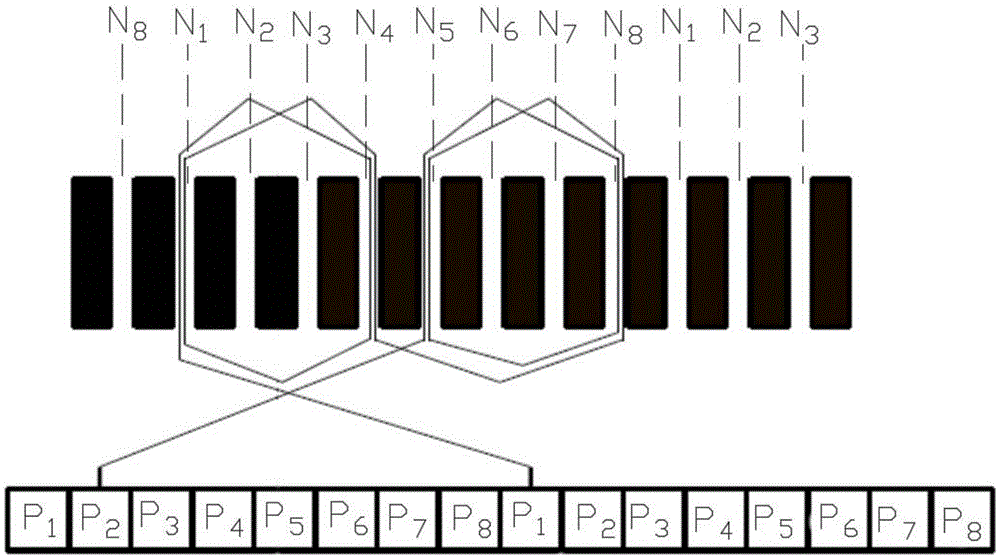
[0020] refer to figure 2 and figure 2 , figure 1 It is a structural schematic diagram of a motor rotor according to an embodiment of the present invention, figure 2 It is a schematic diagram of a motor rotor winding method according to an embodiment of the present invention.

[0021] A meth...


PUM


Abstract

The invention discloses a motor rotor winding method, which comprises a rotor rotating shaft, an insulating sleeve and a coil, wherein the insulating sleeve and the coil sleeve the rotor rotating shaft; the insulating sleeve is sequentially sleeved with a commutator and a winding skeleton; a magnetic pole group is arranged on the outer side surface of the winding skeleton; eight line through grooves are sequentially arranged on the winding skeleton along the circumference; the line through grooves are sequentially numbered N1, N2, N3, N4, N5, N6, N7 and N8 along the circumference; the commutator is sequentially provided with eight brass hooks along the circumference; the brass hooks are sequentially numbered P1, P2, P3, P4, P5, P6, P7 and P8 along the circumference; an included angles between the central line of an armature stack and the central line of the corresponding commutator is 4.5-8.5 degrees; the central line of the commutator is close to a left pole end of a rotor. By double groove-crossing, double groove-crossing is required for each winding of each hook, so that the resistance of a motor rotor winding is evenly distributed; the stalling torque deviation of the motor is relatively small; the energy loss of the motor is reduced; and the service lifetime of the motor is prolonged.

Description

technical field [0001] The present disclosure generally relates to the field of auto parts, and in particular to a method for winding a motor rotor. Background technique [0002] As people have higher and higher requirements for the safety, comfort and reliability of automobiles, the design of the door accessories, which are the main accessories of the car body, is the key to the design of the car door. Automobile door and window glass not only needs to ensure that the driver has enough viewing angles to drive and drive safely; at the same time, in order to meet the needs of riding comfort, the position of the glass often needs to be adjusted, so the range of glass adjustment and the flexibility and convenience of manipulation become important performances. index. The mechanism that ensures the flexible adjustment of automobile glass is the glass regulator, which is also an important part of automobile safety and comfort. [0003] The micro motor is the heart of the automo...

Claims


Application Information

Patent Timeline
Patent Type & Authority Applications(China)
IPC IPC(8): H02K15/09
CPCH02K15/09
Inventor 张发良束庆林
Owner HAIAN LIANKE AUTOMOBILE PARTS
Why Eureka
Try Eureka