Underwater visible light communication system and method
A visible light communication and visible light technology, applied in the field of communication, can solve the problems of low information acquisition efficiency of underwater unmanned robots and low transmission speed of acoustic wave wireless communication, and achieve the effect of improving information acquisition efficiency and timeliness
- Summary
- Abstract
- Description
- Claims
- Application Information
AI Technical Summary
Problems solved by technology
Method used
Image

Examples
Embodiment 1
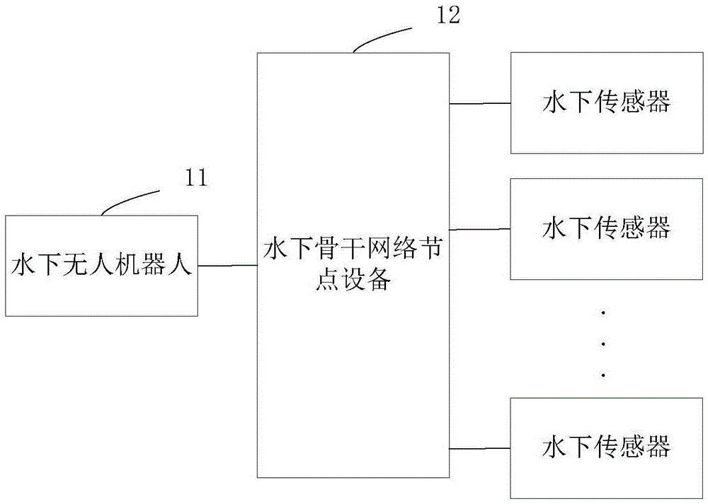
[0049] See figure 1 , which shows a schematic diagram of the logical structure of the underwater visible light communication system provided by the present application. The underwater visible light communication system includes: an underwater unmanned robot 11, an underwater backbone network node device 12, and a plurality of different underwater sensors .
[0050] The underwater backbone network node device 12 communicates with each of the underwater sensors through optical fiber communication.
[0051] In this embodiment, since the sensors deployed underwater can collect surrounding information without autonomous movement, optical fibers are used to connect the underwater sensors to the underwater backbone network node device 12, so that the underwater backbone network node device 12 is connected to the Each of the underwater sensors is communicatively connected through optical fiber communication. Optical fiber transmission is less affected by the underwater environment, ...
Embodiment 2
[0078] This embodiment provides an underwater visible light communication method, based on the underwater visible light communication system shown in Embodiment 1, please refer to Figure 5 , which shows a flow chart of the underwater visible light communication method provided by the present application, which may include the following steps:
[0079] Step S51: The underwater backbone network node device receives the task allocation instruction sent by the underwater unmanned robot, and forwards the task allocation instruction to the corresponding underwater sensor.
[0080] Step S52: The underwater backbone network node device obtains the information collected by each of the underwater sensors.
[0081] In this embodiment, the underwater backbone network node device acquiring the information collected by each of the underwater sensors may specifically be that the underwater backbone network node device regularly acquires the information collected by each of the underwater se...
PUM
 Abstract
Description
Claims
Application Information
 - Generate Ideas
- Intellectual Property
- Life Sciences
- Materials
- Tech Scout
- Unparalleled Data Quality
- Higher Quality Content
- 60% Fewer Hallucinations
Browse by: Latest US Patents, China's latest patents, Technical Efficacy Thesaurus, Application Domain, Technology Topic, Popular Technical Reports.
© 2025 PatSnap. All rights reserved.Legal|Privacy policy|Modern Slavery Act Transparency Statement|Sitemap|About US| Contact US: help@patsnap.com