Multi-air-flue cyclone dust collector

A vacuum cleaner and multi-air duct technology, applied in vacuum cleaners, suction filters, cleaning equipment, etc., can solve problems such as deficiencies, and achieve the effects of comprehensive functions, strong cleaning ability and good overall stability.

Active Publication Date: 2016-06-08
NINGBO HAIJI ELECTRIC APPLIANCE
View PDF7 Cites 4 Cited by
  • Summary
  • Abstract
  • Description
  • Claims
  • Application Information

AI Technical Summary

Problems solved by technology

However, the current vacuum cleaners are still lacking in the setting of

Method used


Image

  • Multi-air-flue cyclone dust collector
  • Multi-air-flue cyclone dust collector
  • Multi-air-flue cyclone dust collector

Examples


Embodiment 1

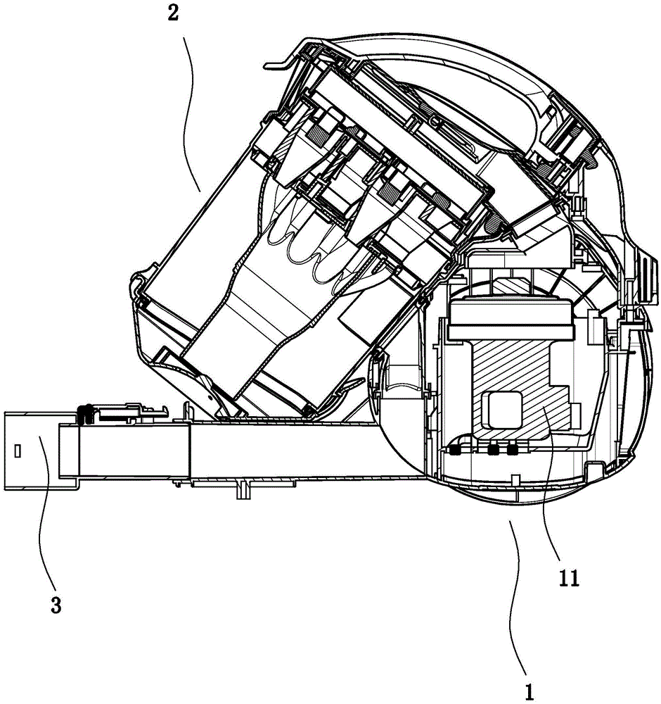
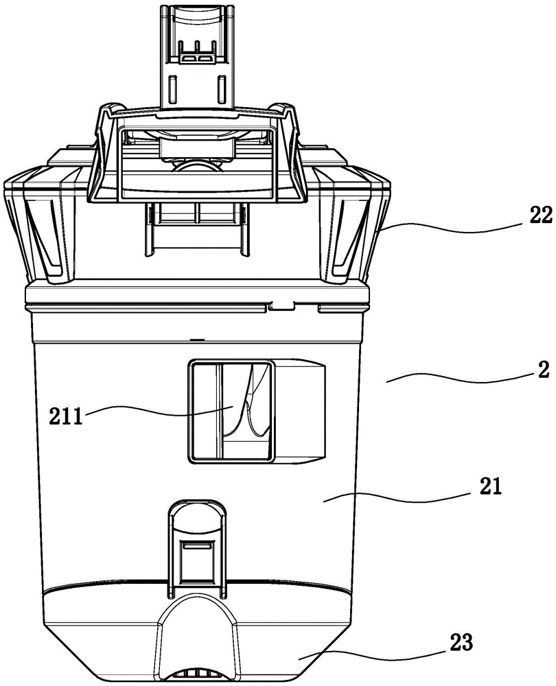
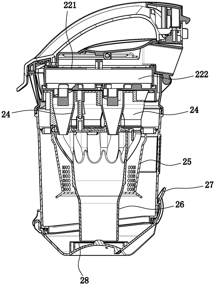
[0025] Embodiment 1: as Figure 1 to Figure 4 In the shown embodiment, a multi-air channel cyclone vacuum cleaner includes a main body 1 and a suction motor 11. The main body is provided with a dust cup body 2 and a suction port 3 for docking with a dust suction pipe. The dust cup The body includes a cup body 21, a cup cover 22 cooperating with the cup body, and a cup bottom 23 cooperating with the cup body. The cup body is provided with a cup body air inlet connected to the suction seat, and a number of shunting cyclone cones are arranged in the dust cup body. 24. The split cyclone cone is provided with a tangential air inlet branch pipe 242 connected to the inside of the split cyclone cone. Both the upper and lower ends of the split cyclone cone are open and the upper opening is larger than the lower opening. The middle air duct is connected with the air inlet end of the suction motor, and the air outlet end of the suction motor is connected with the outer air outlet on the ...

Embodiment 2

[0028] Embodiment 2: the basic structure and implementation mode of this embodiment are the same as embodiment 1, and its difference is, as Figure 5 to Figure 8 As shown in , it also includes a dust-absorbing mop, which is connected to the suction socket through a dust-absorbing pipe. The ground mop base is provided with several rear ground wheels 42 and at least one front ground wheel 43, the bottom of the ground mop base is provided with a direct suction port 44, the air intake direction of the direct suction port is upward, and the ground mop base is provided with a ground mop inner air duct 45. The inner air duct of the mop is connected to the direct suction inlet, the elbow pipe is connected to the inner air duct of the mop, and the mop base is provided with a brush bar 461 for scrubbing the ground, and the brush bar is located in front of the direct suction inlet. The rear ground wheel and the front ground wheel are conveniently dragged and moved on the cleaning surface...


PUM


Abstract

The invention discloses a multi-air-flue cyclone dust collector which comprises a main dust collector body, a suction motor, a dust cup body and a suction port base. The dust cup body comprises a main cup body, a cup lid and a cup bottom. A cup body air inlet is formed in the main cup body. A plurality of flow division cyclone conical cylinders are arranged inside the dust cup body. Tangent air inlet branch pipes are arranged on the flow division cyclone conical cylinders. Openings are formed in the upper and lower ends of the flow division cyclone conical cylinders, and the opening in the upper end of each flow division cyclone conical cylinder is larger than the opening in the lower end of the flow division cyclone conical cylinder. The opening in the upper end of each flow division cyclone conical cylinder is communicated with the air inlet end of the suction motor through a middle air flue. The air outlet end of the suction motor is communicated with an outer exhaust port in the main dust collector body. A filter frame body is arranged in a lid air flue. An air inlet sponge is arranged on the filter frame body. The multi-air-flue cyclone dust collector has the advantages that the air flue is reasonable in structure, and dust separation and collection can be sufficiently completed; the dust suction capacity is high, the filtering effect is good, and the exhaust cleanness can be ensured; the mop anti-collision protection function is achieved, the efficient cleaning capacity for the foot of a wall and other dead corners is achieved, and comprehensive functions are achieved; the overall stability is good, and noise is small.

Description

technical field [0001] The invention belongs to the technical field of vacuum cleaners, in particular to a cyclone vacuum cleaner with multiple air channels. Background technique [0002] With the development of the times and the improvement of living standards, vacuum cleaners, especially household vacuum cleaners, have been widely used. A vacuum cleaner is an electrical appliance that uses a motor (suction motor) to generate negative air pressure in a sealed housing to suck in dust or garbage. The main function of the current vacuum cleaner is to recycle and clean up the dust and garbage on the floor, carpet, etc. in the home. However, the current vacuum cleaners are still lacking in the setting of the air duct, the separation ability and efficiency of dust and air, and the like. Contents of the invention [0003] In order to overcome the deficiencies in the prior art, the present invention provides a filter with reasonable structure, which can effectively complete fun...

Claims


Application Information

Patent Timeline
IPC IPC(8): A47L9/16
CPCA47L9/1608A47L9/1625
Inventor 周荣郑良宝
Owner NINGBO HAIJI ELECTRIC APPLIANCE
Why Eureka
Try Eureka