Casting gating system

A pouring system and pouring cup technology, which is applied in the field of sand casting, can solve the problems of unfavorable molten iron casting yield, increase of return material, increase of molten iron buffer pit volume, etc., so as to reduce internal defects, improve casting yield and reduce volume Effect

Inactive Publication Date: 2016-06-08
四川逢顺商贸有限公司
View PDF0 Cites 7 Cited by
  • Summary
  • Abstract
  • Description
  • Claims
  • Application Information

AI Technical Summary

Problems solved by technology

There is a certain distance between the two main runners, and the volume of the molten iron buffer pit will increase accordingly, resulting in an increase in the return material, which is not conducive to the yield of molten iron castings

Method used


Image

  • Casting gating system

Examples


Embodiment

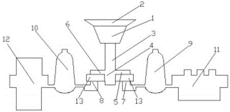
[0009] Example: According to figure 1 As shown, a casting pouring system includes a sprue cup 1, a buffer pit 2 is arranged above the sprue cup 1, and a main runner 3 is connected to the bottom of the sprue cup 1, and the main sprue 3 The bottom end of the T-shaped tee 4 is provided with a T-shaped tee 4, the gate at the right end of the T-shaped tee 4 is connected with the first runner 5, and the gate at the left end of the T-shaped tee 4 is connected with the second runner 6, so The first runner 5 is connected to the first sprue 7, the second runner 6 is connected to the second sprue 8, the first runner 7 is connected to the first riser 9, and the first riser The port 9 finally communicates with the cavity of the first sand mold 11 , the second sprue 8 is connected with the second riser 10 , and the second riser 10 finally communicates with the cavity of the second sand mold 12 . When the molten iron is poured, it is first poured into the buffer pit 2 and filled quickly. Th...


PUM


Abstract

The invention relates to a casting gating system which comprises a pouring cup. A buffer pit is arranged in the upper portion of the pouring cup. The lower portion of the pouring cup is connected with a main pouring gate, and the bottom end of the main pouring gate is provided with a T-type tee joint. A sprue in the right end of the T-type tee joint is connected with a first transverse pouring gate. A sprue in the left end of the T-type tee joint is connected with a second transverse pouring gate. The first transverse pouring gate is connected with a first straight pouring gate. The second transverse pouring gate is connected with a second straight pouring gate. The first straight pouring gate is connected with a first riser which communicates with a cavity of a first sand mould. The second straight pouring gate is connected with a second riser which communicates with a cavity of a second sand mould finally. According to the casting gating system, on the premise of not affecting the pouring quality, the two cavities share one main pouring gate, and the volume of the buffer pit is reduced while pouring of molten iron, so that the pouring speed is increased, internal defects are reduced, the rate of finished molten iron castings is increased, and the casting cost is lowered.

Description

technical field [0001] The invention relates to the field of sand casting, in particular to a casting pouring system. Background technique [0002] In the casting production process, the existing sand mold specifications are divided into two types, one is the same size as the sand box, called one-sided type, and the other is 1 / 2 the size of the sand box, called half-sided type, One main runner is usually set when using one-sided mold molding, and two main runners are set when using half-sided mold molding. There is a certain distance between the two main runners, and the volume of the molten iron buffer pit will increase accordingly, resulting in an increase in the return material, which is not conducive to the yield of molten iron castings. Contents of the invention [0003] The technical problem to be solved by the present invention is to provide a casting gating system which is simple in structure, convenient and practical, aiming at the deficiencies of the above-menti...

Claims


Application Information

Patent Timeline
Patent Type & Authority Applications(China)
IPC IPC(8): B22C9/08
Inventor 郭逢喜
Owner 四川逢顺商贸有限公司
Why Eureka
Try Eureka